Ethernet link aggregation configuration, Overview, Basic concepts – H3C Technologies H3C WX3000E Series Wireless Switches User Manual
Page 32
23
Ethernet link aggregation configuration
This chapter includes these sections:
•
•
Ethernet link aggregation configuration task list
•
Displaying and maintaining Ethernet link aggregation
•
Ethernet link aggregation configuration examples
NOTE:
•
The term "switch" or "device" in this chapter refers to the switching engine on a WX3000E wireless
switch.
•
The WX3000E series comprises WX3024E and WX3010E wireless switches.
•
The port numbers in this chapter are for illustration only.
Overview
Ethernet link aggregation, or simply link aggregation, combines multiple physical Ethernet ports into one
logical link, called an aggregate link. Link aggregation delivers the following benefits:
•
Increases bandwidth beyond the limits of any single link. In an aggregate link, traffic is distributed
across the member ports.
•
Improves link reliability. The member ports dynamically back up one another. When a member port
fails, its traffic is automatically switched to other member ports.
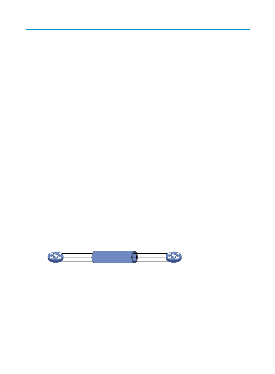
As shown in
, Device A and Device B are connected by three physical Ethernet links. These
physical Ethernet links are combined into an aggregate link, Link Aggregation 1. The bandwidth of this
aggregate link is as high as the total bandwidth of these three physical Ethernet links. At the same time,
the three Ethernet links back up one another.
Figure 4 Diagram for Ethernet link aggregation
Basic concepts
Aggregation group, member port, aggregate interface
Link aggregation is implemented through link aggregation groups. An aggregation group is a group of
Ethernet interfaces combined together, which are called member ports of the aggregation group. For
each aggregation group, a logical interface, called an aggregate interface, is created. To an upper
layer entity that uses the link aggregation service, a link aggregation group looks like a single logical link
and data traffic is transmitted through the aggregate interface.
Eth1/2
Eth1/1
Eth1/3
Link aggregation 1
Eth1/2
Eth1/1
Eth1/3
Device A
Device B