Wiring power inputs – Westermo MRI-128-F4G-PSE24 User Manual
Page 9
5
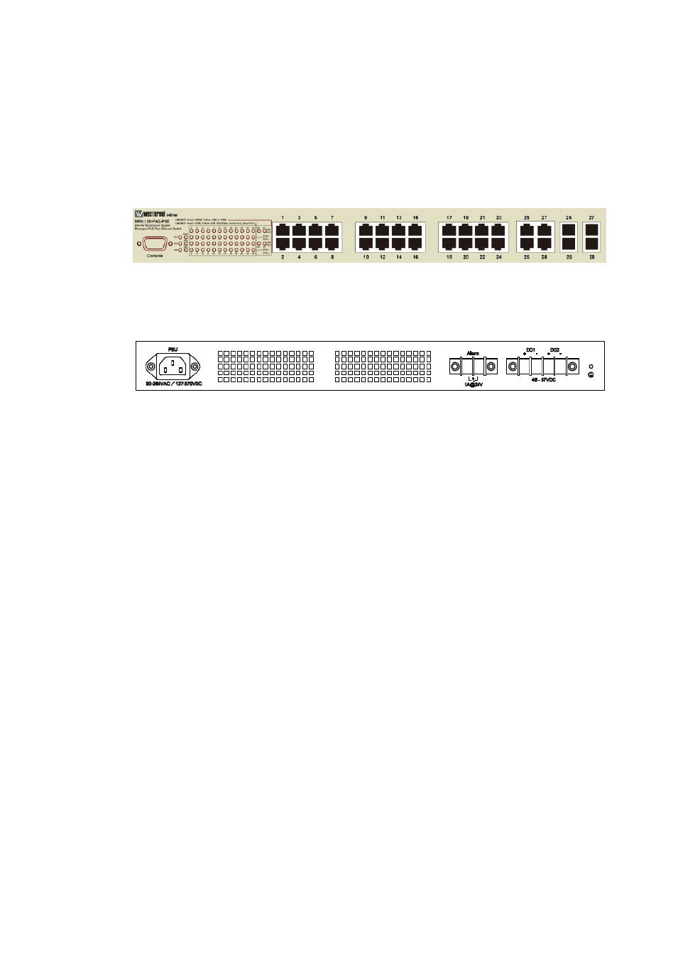
Panel Layout
The front panel includes up to 24 10/100Mbps Fast Ethernet ports, 4 combo
Gigabit Ethernet ports, SFP slot, RS-232 console port, System / Combo Port LED
and up to 24 PoE LED.
Diagram: MRI-128-F4G-PSE/24
The back panel consists of 2 DC power inputs, 1 AC Input, 1 Relay Output.
2.2
Wiring Power Inputs
The switch provides two types power input, AC power input and DC power input. It
also provides redundant or aggregated power inputs, depending on the voltage of
power input. If there are over two power inputs are connected with different
voltages, it will be powered from the highest connected voltage (redundant power).
If the voltages of power inputs are the same, the total power output will be
aggregated (aggregaged power).
AC Power Input
Connect the attached power cord to the AC power input connector, the available AC
power input is range from 90-264VAC.
High Voltage Power Input
The power input support both 90-264VAC and 127-370VDC power input. Connect
the power cord to the PE for Protective Earth, L / V+ for LINE or V+, N/V- for Neutral
or V-. For high power input, tighten the wire-clamp screws to prevent DC wires from
being loosened is must.
DC Power Inputs
The range of the available DC power input is from 46-57VDC. In the IEEE802.3at
mode, the PoE power output is 50~57 VDC, 0.6A, therefore, the suggested DC power
input ranges is 52~57V. In the IEEE802.3af mode, the PoE power output is 44~57
VDC, 0.35A, therefore, the suggested DC power input is 46~57VDC.