Wiring digital output, Wiring earth ground – Westermo MRI-128-F4G-PSE24 User Manual
Page 11
7
MRI-128-F4G-P24
Power
Supply
Type
Input Range
Fuse
Rating
Power Consumption
Min
Max
Worst
Case
Max
48 VDC
46 VDC 57 VDC 1.5A(F)
369.6W
369.6W
53 VDC
52 VDC 57 VDC 1.5A(F)
568W
720W
Table: PoE/PoE Plus Power Supply Specifications
Note 1: (F) Denotes fast-acting fuse, (T) denotes time-delay fuse
Note 2: Power consumption varies based on configuration. 10/100Tx ports
consume roughly 1W less than fiber optic ports
Note 3: For continued protection against risk of fire, replace only with same
type and rating of fuse.
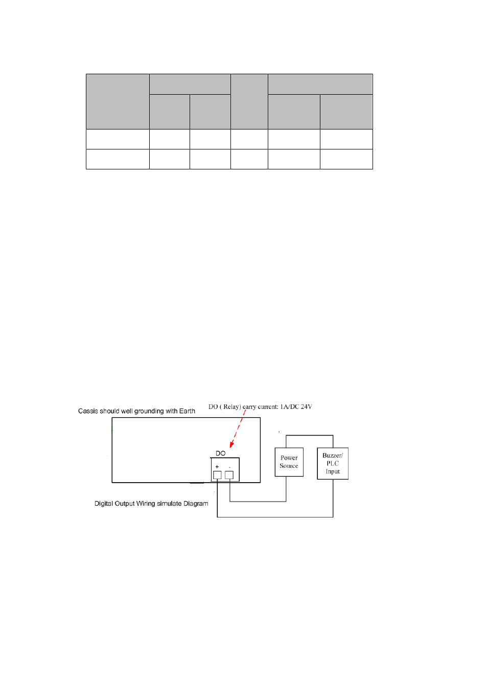
2.4
Wiring Digital Output
The switch provides one digital output, also known as Relay Output. The relay
contacts are energized (open) for normal operation and will close for fault
conditions. The fault conditions include power failure, Ethernet port link break
or other pre-defined events which can be configured.
Wiring digital output is exactly the same as wiring power input introduced in
chapter 2.2.
2.5
Wiring Earth Ground
To ensure the system will not be damaged by noise or any electrical shock, we
suggest you to make exact connection with the switch with Earth Ground.
On the back panel, there is one earth ground screw. Loosen the earth ground
screw using a screw driver; then tighten the screw after earth ground wire is
connected.