Westermo MRI-128-F4G-PSE24 User Manual
Page 65
61
4.4.2 Emergency Power Management
The switch is equipped with dual 48VDC power inputs for providing true network
redundancy. An alarm relay output signals when a power input fails or other
critical events occur. To ensure reliable power delivery, other advanced PoE
power management features include individual port status monitoring,
emergency power management (3 power supply indication inputs for quick
shutdown of ports according to pre-defined priority table in cases where power
supply failure occurs) and voltage/current monitoring and regulation. Power
management allows the switch to determine the exact power draw per port and
to balance each port PoE power output accordingly. This, in turn, allows the
switch to power higher and lower wattage devices according to user-definable
parameters such as maximum available power, port priority (critical, high, low),
and maximum allowable power per port. For the same level priority, the priority
order is decided by port number. The port number sequence of
MRI-128-F4G-PSE/24 from high priority to low priority is 3-4-1-2-7-8-5-6-
11-12-9-10-15-16-13-14-19-20-17-18-23-24-21-22-27-28-25-26.
4.4.3 PD Status Detection
The switch delivers a useful function – PD Status Detection. This provides
automatic detection of a remote device powered by the switch. If the remote
system crashes or is unstable, the switch will perform a system reboot by turning
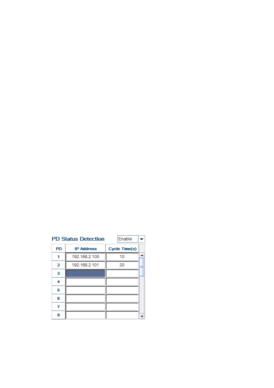
off and on again to trigger the remote device. The following figure shows the Web
configure interface for Power over Ethernet PD Status Detection.
You can enable/disable PD Status Detection function and type in the IP address
that you want to detect. The Cycle Time is the gap per detection. After
configuring, please click the Apply button to enable and perform the functions.