Building circuits—circuit manager menu, Building circuits—circuit manager menu -30 – Verilink DIDCSU 2912 (880-502646-001) Product Manual User Manual
Page 70
DIDCSU T1 Version
3-30
Verilink DIDCSU 2912 User Manual
Figure 3-20 Display Alarm Buffer
When finished reviewing the alarm information, enter “X” to return
to the Main Menu.
Building Circuits—Circuit Manager Menu
To access the Circuit Manager Menu from the Main Menu, enter
“B”.
Use the Circuit Manager Menu to build and maintain logical
connections between ports within a node. The port can be a T1 or
data port. T1 port bandwidth is set using a number of timeslots, 1-
24. The bandwidth for each DS0 is set to 56 kbit/s or 64 kbit/s.
NOTE: Each circuit must include a minimum of one network port
(circuits are not supported from data port to data port).
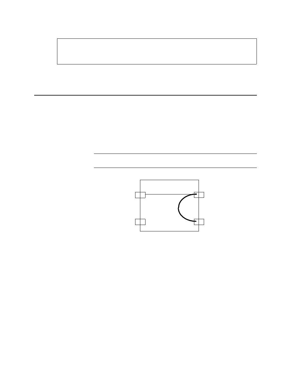
Figure 3-21 Circuit Connections
•
The port line code selection (for example, 56 kbit/s or 64
kbit/s circuits) can limit a circuit’s available bandwidth.
•
Network and data ports must be In Service before being
included in a circuit.
•
When you have named a circuit and identified its source and
destination ports, allocate its source and destination
timeslots.
•
If a card is moved to a different slot all circuits in that card are
discarded when it powers up in a different numbered slot.
[1,1] DIDCSU 2912 > o
[1,1] DIDCSU 2912 > o
[1,1] DIDCSU 2912 > o
[1,1] DIDCSU 2912 > o
DIDCSU 2912 [1,1] AIS Minor Alarm port 1 8-09-96 18:38:35
DIDCSU 2912 [1,1] AIS Minor Alarm port 1 8-09-96 18:38:35
DIDCSU 2912 [1,1] AIS Minor Alarm port 1 8-09-96 18:38:35
DIDCSU 2912 [1,1] AIS Minor Alarm port 1 8-09-96 18:38:35
DIDCSU 2912 [1,1] AIS Threshold Cleared port 1 8-09-96 18:37:17
DIDCSU 2912 [1,1] AIS Threshold Cleared port 1 8-09-96 18:37:17
DIDCSU 2912 [1,1] AIS Threshold Cleared port 1 8-09-96 18:37:17
DIDCSU 2912 [1,1] AIS Threshold Cleared port 1 8-09-96 18:37:17
Press enter to continue
Press enter to continue
Press enter to continue
Press enter to continue
Net 1
Data 1
Net 2
Data 2
A
B
A. Data to T1
B. T1 to T1