T1 cims, E1 cims, Figure 1-3 t1 cim configurations – Verilink DIDCSU 2912 (880-502646-001) Product Manual User Manual
Page 12
DIDCSU 2912 Overview
1-6
Verilink DIDCSU 2912 User Manual
•
External timing source input—The 8-pin mini-DIN connector
optionally receives a square wave signal from an external
timing device. For T1 versions this clock must be at 1.544
Mbit/s, for E1 versions it must be at 2.048 Mbit/s.
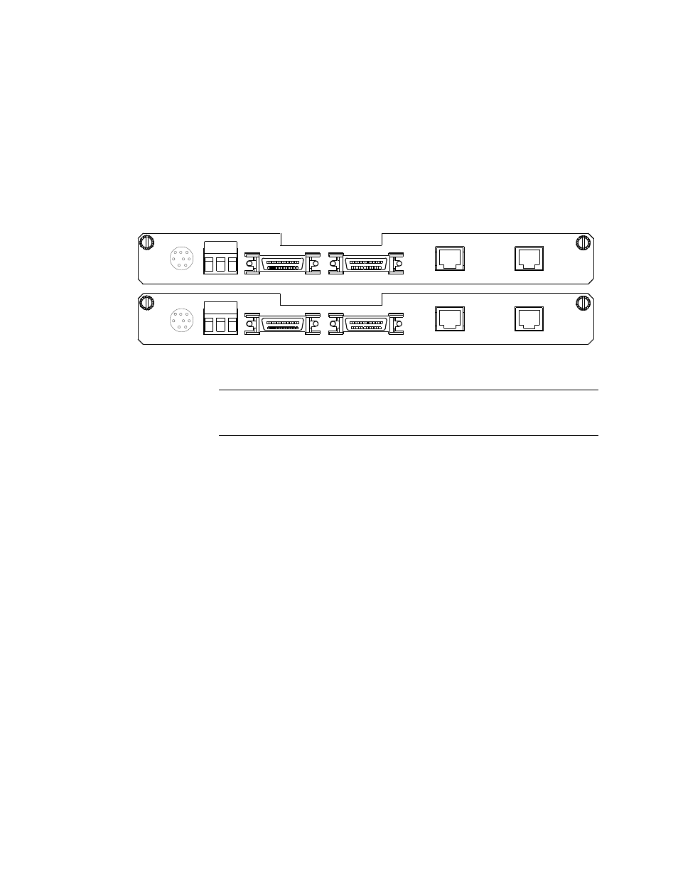
T1 CIMs
The DS-1 CIM 29010 and the DS-1 CIM 29011 support dual RJ-48C
network port connectors and dual V.35 or EIA 530/RS-449
equipment connectors, respectively.
Figure 1-3 T1 CIM Configurations
NOTE: Data Ports use mini-D-sub 26-pin connectors. They require
adapter cables to properly interface with native connectors.
E1 CIMs
E1 CIMs provide the following connectors:
•
Two E1 line ports (either coaxial, DE-9, or RJ-45 connectors)
•
Two data port connections of various protocols (all 26-pin
mini-DIN connectors)
shows all the E1 CIM configurations.
V.35
V.35
INPUT
RELAY
NO COM NC
DATA 2
DATA 1
DS-1
PORT 2
PORT 1
ALARM
EXT TIMING
CIM
2
901
0
3
1
1
-10
13
87
-0
0
1
RS449
RS449
INPUT
RELAY
NO COM NC
DATA 2
DATA 1
PORT 2
PORT 1
ALARM
CIM
29
01
1
3
1
1-
10
13
87-
0
0
2
EXT TIMING
T1 Port 1
T1 Port 2
Data Port 1
Data Port 2
Alarm
Relay
Ext.
Timing
Input
DS-1