Connector interface modules, Connector interface modules -5, Leds – Verilink DIDCSU 2912 (880-502646-001) Product Manual User Manual
Page 11: Management ports
DIDCSU 2912 Overview
Verilink DIDCSU 2912 User Manual
1-5
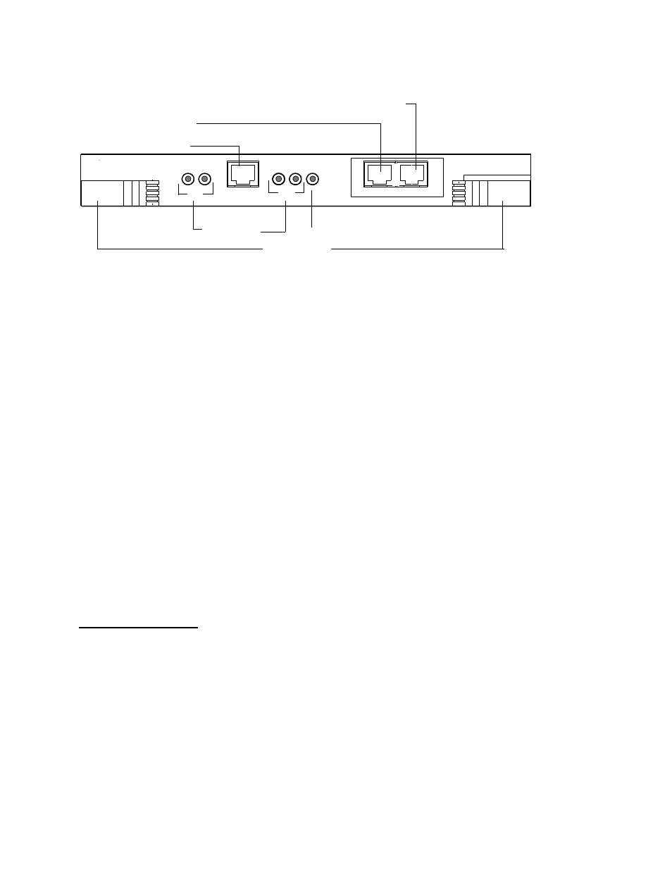
Figure 1-2 DIDCSU Front Panel
LEDs
The DIDCSU front panel’s System LED (SYS) is green when the
module has passed the power-up self-test.
The panel also contains four status LEDs:
•
Two for network port status
•
Two for data port status
Chapters 3 and 4 of this manual define the LEDs and alarms for the
T1 and E1 versions respectively.
Management Ports
Three front panel management ports support management of the
local node.
•
LOCAL
—6-wide modular, direct connection to the Craft
interface using an ASCII terminal or a PC running a terminal
emulator
• PRI
—8-wide modular, RS-232-compliant Primary Management.
Used for ACP bus extension between shelves in a multi-shelf
node.
• EXT
—8-wide modular, RS-232-compliant port for daisy-
chaining multiple AS2000 shelves (ACP-managed modules
only).
Connector
Interface
Modules
Rear connector interface modules (CIMs) provide network ports for
connection to the wide area network facility and data ports for
connection to synchronous serial data terminal equipment (DTE).
They also provide the following connections:
•
Alarm relay—These contacts can be wired to external alarm
equipment. The connector pins provide output as a normally
open (NO) contact, or a normally closed (NC) contact.
MANAGEMENT
SYS
LOCAL
2
NET
DATA
1
DIDCSU 2912
Port LEDs
System LED
PRI
EXT
1
2
ACP Management communications port to extend bus to next shelf
Primary ACP Management port for connection of preceeding shelf
Craft Port, RJ-11
Ejector Handles