Verilink DIDCSU 2912 (880-502646-001) Product Manual User Manual
Page 55
DIDCSU T1 Version
Verilink DIDCSU 2912 User Manual
3-15
•
LLB—Local Loopback
•
TM—Test Mode
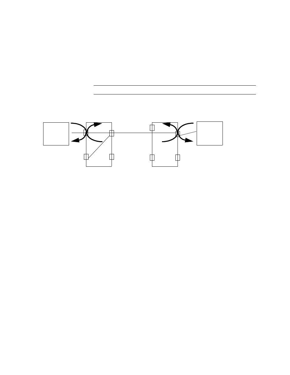
During normal operation, these leads should be set to LOW. By
connecting a test set to the data port, the RLB and LLB leads can be
forced HIGH individually. The resulting loopbacks are shown in the
following diagram. The status display will change to HIGH for these
leads.
NOTE: These leads are only useful in DCE mode.
Figure 3-10 Loopbacks
•
In DCE mode the leads TM, DSR, DCD, and CTS can be forced
HIGH while connected to a test set to check that each lead is
operating properly.
•
In DTE mode, the leads DTR, RTS, LLB, and RLB can be forced
HIGH while connected to a test set to check that each lead is
operating properly.
, the parameters listed in the dashed box are port
status listings.
•
The first four lines show the state of the incoming handshake
leads. HIGH means incoming handshake signals are detected
on that lead, and LOW means no handshake signaling is
detected. In DCE mode, if the TM lead is HIGH it indicates that
the data port is in test mode, whereas in DTE mode, it
indicates the state of the equipment.
•
If LOS detection (above) is enabled, Cable present indicates
that the DSU "sees" a signal from the DTE on the Data Terminal
Ready (DTR) lead. If LOS detection is disabled, this field does
not indicate any factual information and should be ignored.
•
DPL Loopback shows whether a data port loopback has been
enabled or disabled (in the Data Port Diagnostics Menu).
•
If a test pattern has been enabled in the Data Port Diagnostics
Menu, QRSS (Quasi-Random Signal Sequence) is displayed in
this field.
DTE
DIDCSU
DIDCSU
DTE
In DTE Mode
N1
P1
N2
P2
P2
P1
Nea
Far
13-
24
1-12
T1/E1
RLB
LLB