NavCom LAND-PAK Rev.N User Manual
Page 29
Technical Reference Manual Rev. N
Blk = All;
Blu = IOP w/Internal Radio
;
Red = IOP & LBM
;
Grn = Engine only
27
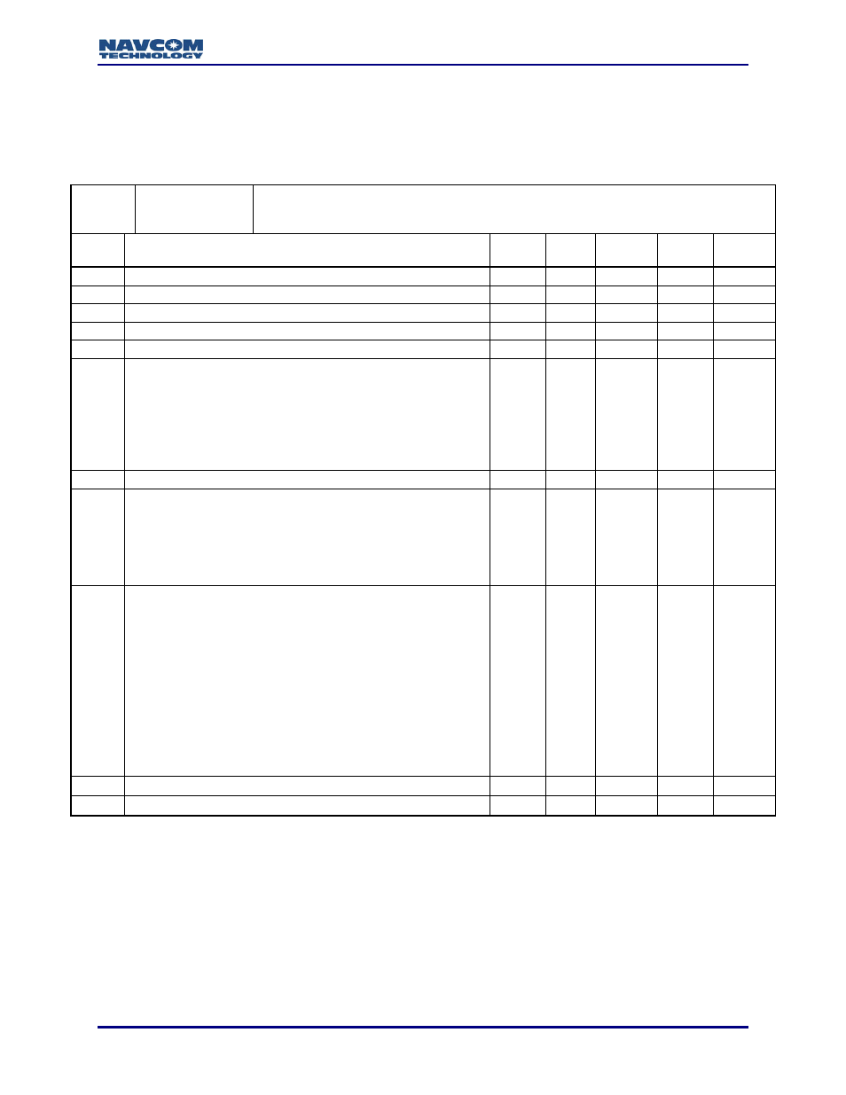
0x14 - Channel, Mode and Raw Data assignment - 8 bytes
This command configures the Channel Mode and Raw Data assignment.
1. For multiple command actions, the bits in W1 may be OR’ed.
2. W2 and W3 revert to factory settings as default values.
3. In Table 2, N is maximum channel limitation, which can be 6, 9 or 12.
4. On W4, B4 can be OR’ed with others.
Record
Usage
Command - Yes
Response - No
Input: This message is intended for factory use and may cause tracking issues if
improperly implemented
Output:
Ref
Message Field Description
Data
Type
Units Range Scale
Byte
Count
STX
02
(hex)
U08
1
PRA1 99 (hex)
U08
1
PRA2 66 (hex)
U08
1
ID
14
(hex)
U08
1
Length
0x0008
U16
2
W1
Command Action
B1=0: Do not store in NVRAM
1: Store in NVRAM
B2=0: Do not use ACK/NAK
1: Use ACK/NAK
B3=0: Use Commanded Values
1: Use Default values
U08
1
W2
Reserved
U08
1
W3
Raw Data Output Selection
B0: C/A Code Measurements
B1: P1 Code Measurements
B2: P2 Code Measurements
B3: L1 Carrier Measurements
B4: L2 Carrier Measurements
U08
1
W4
Channel Moding
B0: CA Mode
(No P1/P2/L2 Tracking)
B1: Extended CA Mode
(Use P2CA Slot for additional CA Tracking
channels)
B2: CA/P1 Mode
(P1 Tracking Required)
B3: CA/P1/P2 Mode
(P1/P2 Tracking Required)
B4: WAAS Mode
(WAAS Channels may Track WAAS Satellites)
U08
1
CKSM Checksum
U08
1
ETX
03
(hex)
U08
1