Data frame, Data frame …… 6-12 – Measurement Computing DBK70 User Manual
Page 78
6-12 Fundamentals of Obtaining Vehicle Data
928494
DBK70 User’s Manual
For any one record in the DBK70 database, the Filter and Message fields are only loosely related.
For non-DDP applications, the Message field is used to transmit messages onto the network at a rate
specified by the Update Rate to stimulate a response that is captured by the Filter. Regardless of whether
the network module responds or not, the Message will continue to be transmitted at the Update Rate.
Transmission of the Message and capturing the response are completely separate DBK70 tasks.
The Message field is unaware that the Filter field is seeking a specific response, just as the Filter field is
unaware that the Message field is requesting a response.
Due to this loose coupling between Message and Filter, the DDP messages can be packaged into the
Message fields of the 3 DBK70 channels in a variety of different ways. The following is an example of one
possible scheme.
Message:
C410F12C014A1165 C410F12C01591310
Filter:
C400F1FF10FF6AFF01FF
Update rate: -1
Index:
40
Length:
16
Channel 1 will send 2 definition messages to
add 2 PIDs to our defined DDP, identified
as DPID#1. The individual messages are
separated by one space.
We’ll set its Update Rate to –1 so that the
DBK70 will send this message only once –
either at power-up or if a timeout occurs.
Message:
C410F12C01621671 C410F12A0401
Filter:
C400F1FF10FF6AFF01FF
Update rate: -1
Index:
56
Length:
8
Channel 2 will send 1 more definition
message to add the 3
rd
PID to DPID#1, then
the request message to get the network
module broadcasting our newly defined
DPID#1. We’ll set its Update Rate to –1 so
that the DBK70 will send this message only
once.
Message:
C410F13F
Filter:
C400F1FF10FF6AFF01FF
Update rate: 3000
Index:
64
Length:
16
Channel 3 will send the Tester Present
message every 3 seconds so that the
network module will continue to transmit
DPID#1.
Note that the Filter for all three channels is
identical because they’re all looking for the
same DPID#1. Once found, each channel
will find its data using the Index and
Length fields.
Obtaining Vehicle Data for CAN, Including J1939 & OBD CAN
All CAN communication is executed in data packets called frames. Four frame types are defined;
Data Frame, Remote Frame, Error Frame, and Overload Frame. For the purpose of using the DBK70 to
collect data from a CAN network, only the Data Frame is relevant.
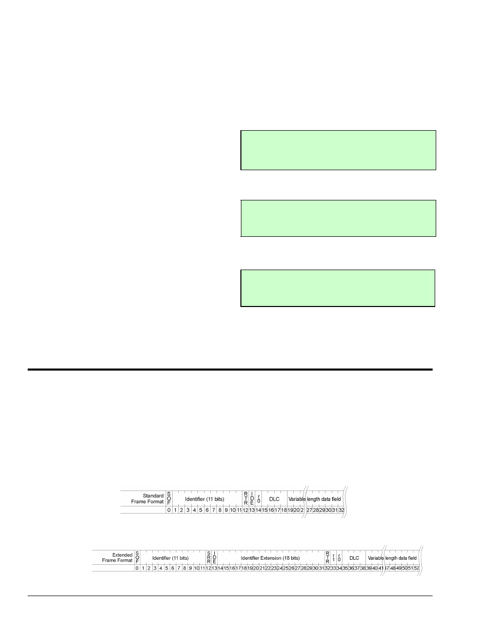
Data Frame
A Data Frame is used by nodes on the network to transmit data to other nodes. It consists of header
information and a variable length data field. Two header formats are described in the CAN specification;
Standard Format (11-bit) and Extended Format (29-bit). Most newer systems use the Extended Format
exclusively.
Standard Data Frame
Extended Data Frame