Measurement Computing DBK70 User Manual
Page 17
DBK70 User’s Manual
927994
System Setup 3-7
• The Daq* sequencer selects the channel and gain by controlling multiplexers (MUX) and
programmable gain amplifiers (PGA) in both the Daq* and the DBK. The sequencer uses 4 expansion
address lines to provide 16 unique channel addresses for each base channel.
• The DBK70 multiplexer selects 1 of 16 (max) channels as directed by the sequencer. The selected
signal goes to the channel-selection jumper, and then to the Daq* via P1.
• The Daq* multiplexer selects 1 of 16 base channels from P1 input lines as directed by the sequencer.
The selected signal goes to the PGA and then to the A/D converter (A/D).
• The P1 interface has a signal line for each of the 16 base channels.
• The JP1 channel select jumper in the DBK70 can be placed on pins for channel 0 through channel 15.
Each DBK70 in the system must occupy a different base unit channel. The factory default setting for the
JP1 jumper is channel 0.
Reference Note:
Refer to the DaqView or LogView documentation for instructions on how to inform the
software of the presence of DBK modules and cards.
Using the steps described in the DaqView or LogView documentation, the user must provide the location
of the JP1 jumper to the software.
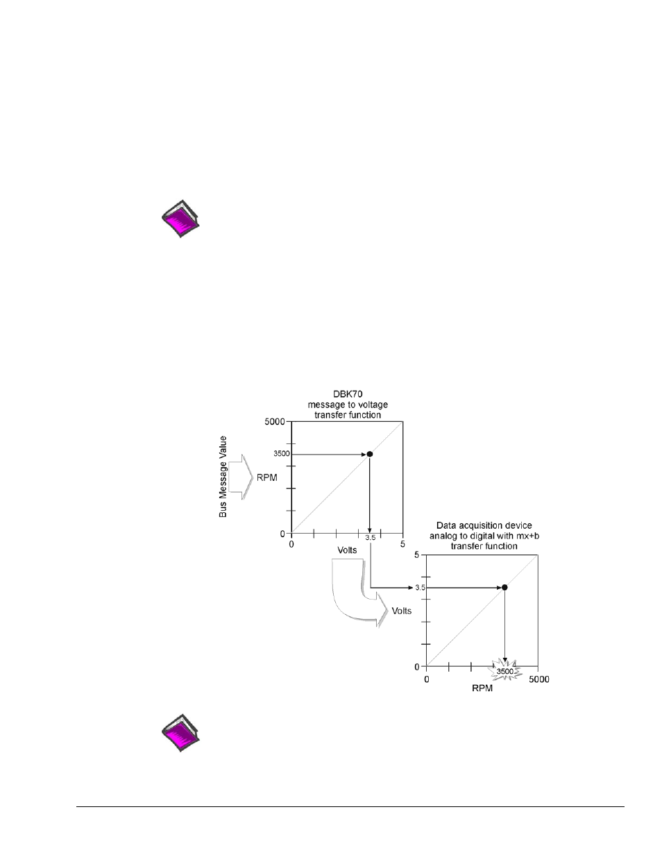
In DaqView or LogView, use the mx+b (scale and offset) feature to convert the DBK70 voltage values into
engineering units. For example, if the DBK70 is capturing vehicle RPM in the range of 0 to 5000 RPM and
scaling the result to 0 to 5 volts, setting the “m” in WaveView to 1000 will convert the incoming voltage to
RPM. This technique can be used in any data collection software package to convert the DBK70’s output
voltage to engineering units.
Reference Note:
mx + b values are included in a Microsoft Excel file: mx+b values.xls. The file is
located in the root directory of your DBK Configuration CD (p/n 1056-0600).