Vehicle diagnostic connectors, Vehicle diagnostic connectors …… 4-5 – Measurement Computing DBK70 User Manual
Page 23
DBK70 User’s Manual
919092
Hardware Reference 4-5
Vehicle Diagnostic Connectors
The J1962 Vehicle Diagnostic Connector is required on all new automobiles sold in the USA after model
year 1995. It may also be available on a few model year ‘94 and ‘95 vehicles sold in the USA. Tentatively,
it will also be required on all new automobiles sold in the EC in calendar year 2000 and later.
Different vehicle manufacturers may give different names to the vehicle’s diagnostic connector. Some may
call it the ALDL connector, the Class 2 connector, the SCP connector, the 16-Way, the J1850 connector, or
the diagnostic connector.
The vehicle’s diagnostic connector is typically mounted under the instrument panel on the driver’s side of
the vehicle. The connector is typically mounted in or near a center console or under the instrument panel on
the driver’s side of the vehicle.
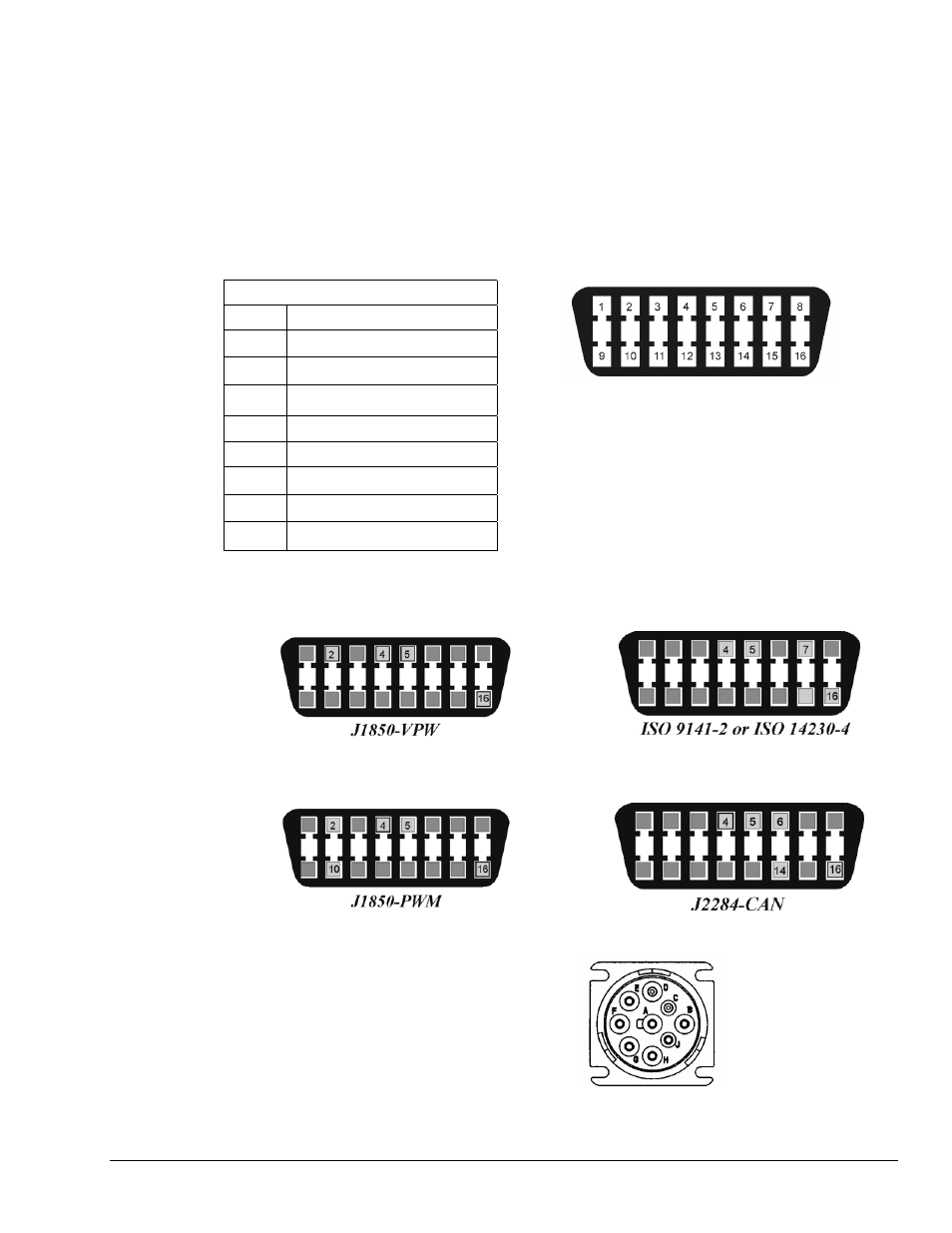
16-Way Diagnostic Connector Pinout
Pin# Description
2 J1850
Bus
(+)
4 Chassis
Ground
5 Signal
Ground
6 CAN
High
7
ISO 9141-2 K Line
10 J1850
Bus
(-)
14 CAN
Low
16 Battery
Power
16-Way Diagnostic Connector*
The 16-pin diagnostic connector is known by many different
names. These include, but are not limited to: the 16-Way,
J1962, J1850, the Class 2, and the ALDL connector.
*Note: The 9-pin J1939 diagnostic connector, used in heavy-
duty vehicles, is discussed on page 4-7.
On year 1996 and later vehicles sold in the U.S., you can tell, with some level of certainty, which protocol
the vehicle uses. This is done by examining the metallic contacts in the OBD II connector, as indicated in
the following figures. Note that heavy-duty vehicles, such as busses, tractors, and trucks typically make
use of the J1939 diagnostic connector. J1939 is discussed on page 4-7.
J1850-VPW
--The connector should have metallic
contacts in pins 2, 4, 5, and 16, but not 10.
ISO 9141-2 or ISO 14230-4
--The connector
should have metallic contacts in pins 4, 5, 7,
and 16.
J1850-PWM
--The connector should have metallic
contacts in pins 2, 4, 5, 10, and 16.
J2411-CAN
-The connector should have metallic
contacts in pins 2, 4, 5, 6, 10, 14, and 16.
J1939
– The J1939 diagnostic connector should have
metallic contact pins in A, B, C, D, E, F, and G. This
connector is discussed in the section, J1939 Vehicle
Bus Cable, CA-218, on page 4-7.
J1939