Range low / range high, Analog to engineering units conversion – Measurement Computing DBK70 User Manual
Page 57
PidPRO & PidPRO+
919092
5-27
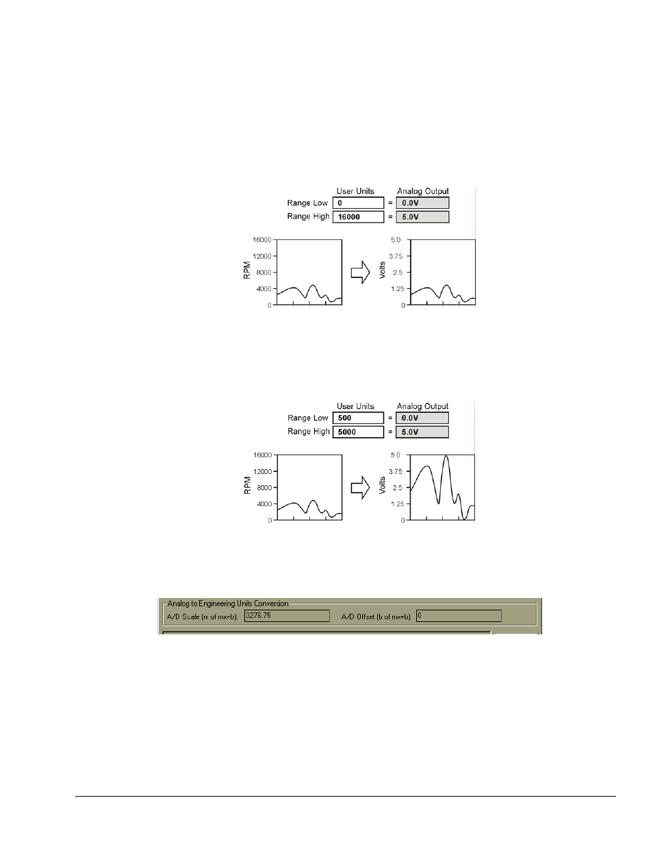
Range Low / Range High
An assigned analog output channel will span 0 to 5V, proportional to the converted value of the captured
binary data. The Range Low and High fields specify the user units values that are associated with the
analog output range. As a default, or if the Set to Limits button is clicked, the range of the analog output
matches the limits of the raw input.
In instances where the realized value of the parameter varies only slightly, relative to the limits of the raw
binary data, the analog output will also vary only slightly, causing poor measurement resolution. For
example, the limits specified for the RPM parameter may be 0 to 16000 RPM, but during your test, the
value may only vary from 500 to 5000. In this case, the analog output will only vary by about
1.35V, which is 27% of the full-scale value of 5V.
To maximize the dynamic range of the 0 to 5V analog output, set the Range Low and High values to the
realized span of the parameter for your application. In the example above, setting the Range Low to 500
and the Range High to 5000 would scale the 0 to 5V output to span only the realized range. With these
settings, 100% of the dynamic range of the 0 to 5V output is used, where 500RPM = 0V and
5000RPM = 5V.
These parameters have no affect on virtual channel assignments because there is no analog output
associated with virtual channels.
Analog to Engineering Units Conversion
Analog to Engineering Units Conversion Panel
Located near the bottom of the Database Item View Window
The section at the bottom of the Database Item View provides useful information for setting up the analog
input channel on your data acquisition product to read the parameter in user units.
The DBK70’s analog output will provide a voltage from 0V to 5V, proportional to the PID value. When
read on an analog input channel of a data acquisition system, the value will be 0V to 5V. IOtech data
acquisition products provide a means of supplying an offset and scale to each channel so that the value
captured will be in user units, e.g., RPM or Degrees C. Sometimes these settings are called mx+b, which
represents the equation for a linear transfer function, where m = scale, and b = offset. Using the A/D
Offset and A/D Scale settings in the fields shown will translate the 0 to 5V signal from the DBK70’s
analog output into the desired user units in your data acquisition system.