Measurement Computing DBK70 User Manual
Page 103

DBK70 Firmware Upgrade Instructions
909192
1056-0902, rev 5.0 3
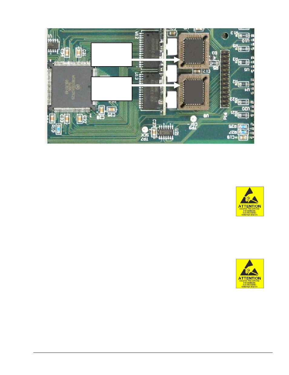
Close-up of the PLCC Socket Locations
Replacing the Chip at U8
1. Using the PLCC extraction tool, carefully remove the old 1056-0301 chip at U8 by placing the tool’s
hooks down into the access holes on opposite corners of the socket. Squeeze the extraction tool and
pull the chip free of the socket. Discard the old chip.
2. Insert the new chip, 1056-0301, into U8 as follows:
(a) Verify correct orientation. The chip’s chamfer must align
with the chamfer on the board’s socket.
(b) Squarely center the new chip over the socket.
(c) Gently push the chip into the socket. The chip should snap into position.
Replacing the Chip at U9
1. Using the PLCC extraction tool (included), carefully remove the old 1056-0300 chip at U9 by placing
the tool’s hooks down into the access holes on opposite corners of the socket. Squeeze the extraction
tool and pull the chip free of the socket. Discard the old chip.
2. Insert the new chip, 1056-0300, into U9 as follows:
(a) Verify correct orientation. The chip’s chamfer must align
with the chamfer on the board’s socket.
(b) Squarely center the new chip over the socket.
(c) Gently push the chip into the socket. The chip should snap into position.
U8
p/n 1056-0301
is located here.
U9
p/n 1056-0300
is located here.
