K-Patents PR-21-S User Manual
Page 72
66
PR-21-S instruction manual
Processor card Remove the Processor Card. Note that all connectors have latches.
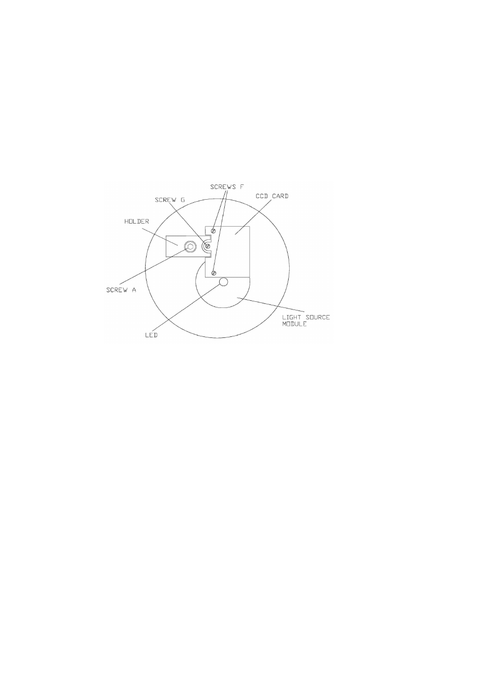
Image detector module Remove Screw A, Figure 7.1. Then the holder can be re-
moved. Gently pull the module out. Be careful not to pull the CCD card. Pull
from the back of the module body. At assembly note the aligning pin. Do not touch
the screw G, because it fixes the CCD card with the CCD element for receiving op-
tical image correctly from the optics inside of the module.
Figure 7.1
Sensor processor
Light source module Remove Screw B, Figure 7.2. Then the module can be pulled
out. (The hole C should always be empty). The emitter assembly is locked by screw
D and can be removed from the module.
Temperature sensor Use fingers to turn the Temperature Sensor (Figure 7.2)
counterclockwise.