2 inline refractometer sensor, 1 sensor description – K-Patents PR-21-S User Manual
Page 15
2 Inline refractometer sensor
9
2 Inline refractometer sensor
2.1 Sensor description
In the K-Patents Process Refractometer Sensor (Figure 2.1) the measurement prism
(A) is flush mounted in the oblique surface near the tip. The light source (B) is a light
emitting diode.
K-Patents Process refractometer uses a CCD element (C) which has 3648 photocells
in a row integrated on one chip.
INSTRUCTION MANUAL FOR K-PATENTS PR-01-S (-AX/FM/CS)
DOCUMENT/REVISION No. INM 1/14
Effective: May 15, 2009
8
2.4. SENSOR DESCRIPTION
In the K-Patents Process Refractometer Sensor (Figure 2.40) the measurement prism (A) is flush mounted
in the oblique surface near the tip. The light source (B) is a light emitting diode.
K-Patents Process Refractometer uses a digital image detector (C). The image detector consists of 256
photocells in a row integrated on one chip.
A
B
C
D
E
F
G
Figure 2.40
Sensor structure.
The image detector output is a pulse train as shown in Figure 2.41. This number of high pulses corresponds
to the position of the shadow edge in the optical image. The number of high pulses is a direct measure of
the critical angle. The image digitizer (E) transforms this pulse train to a serial digital signal. This serial
signal transmits a package containing a complete description of the optical image and temperature data to
the Indicating transmitter.
For automatic temperature compensation, the sensor tip contains a process temperature probe (F).
The digital image sensor (C) is separated from the process heat by fiber optics (D) and the thermal isolation
(G). It is housed in the air-cooled sensor head.
a. Optical image
b. Detector window and the photocells
c. Pulse train from the detector.
a
b
c
TIME
V
Figure 2.41
Image detector system.
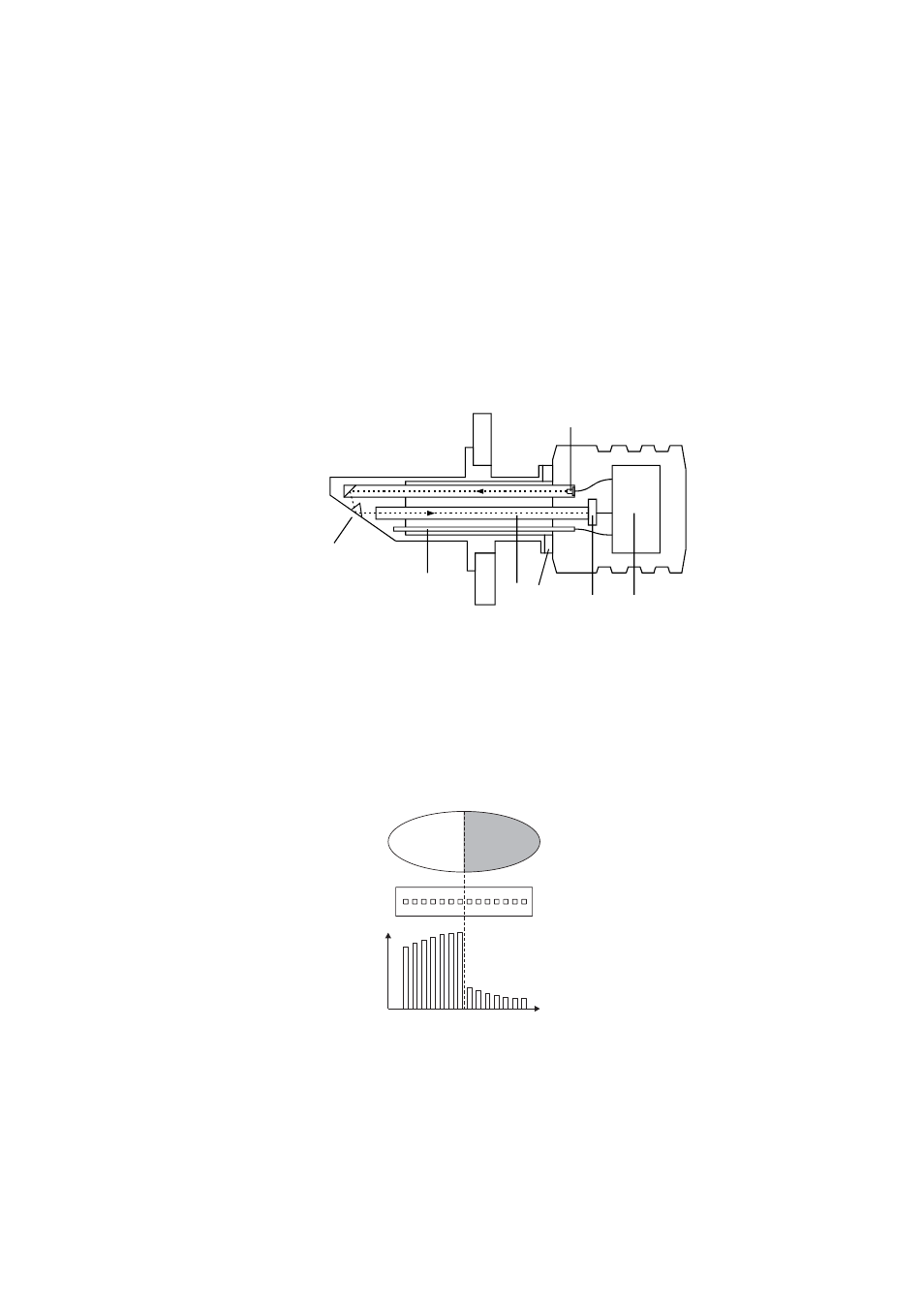
Figure 2.1
Sensor structure
The image detector output is a pulse train as shown in Figure 2.2. This number of
high pulses corresponds to the position of the shadow edge in the optical image. The
number of high pulses is a direct measure of the critical angle. The sensor processor
card (E) receives the raw data from CCD element (C) and the temperature probe (F).
The digital image sensor (C) is separated from the process heat by fiber optics (D) and
the thermal isolation (G). It is housed in the air-cooled sensor head.
a. Optical image
b. CCD element
c. CCD output
V
Figure 2.2
Image detector system