K-Patents PR-21-S User Manual
Page 28
22
PR-21-S instruction manual
6
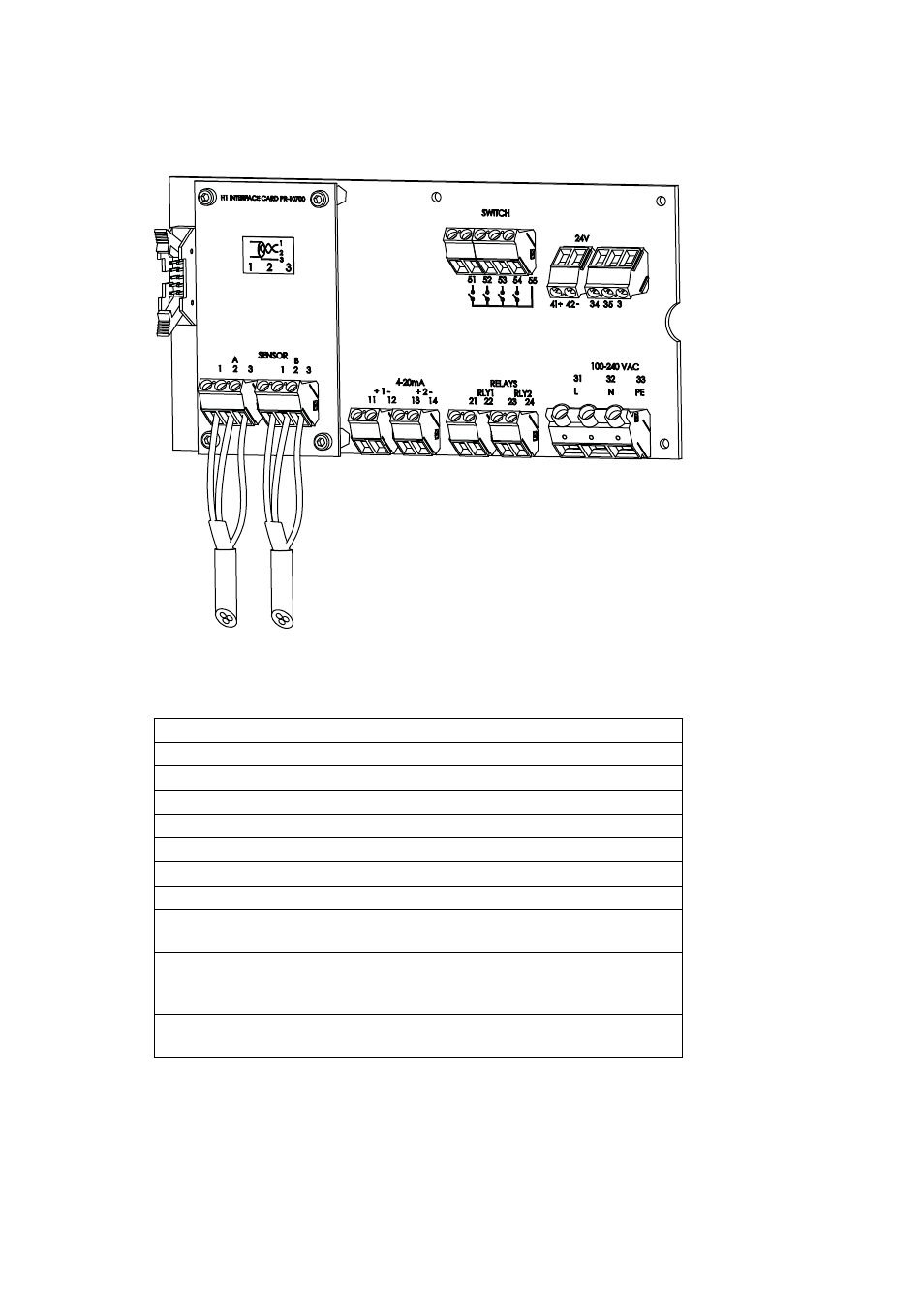
Figure 3.6
The Motherboard of the Indicating transmitter
Description of the terminals on the H1 interface card PR-10701 and on the Transmit-
ter motherboard PR-10600 (Figure 3.6):
On H1
A 1 2 3
Connection for Sensor A, signal wires (1, 2), cable shield (3).
B 1 2 3
Connection for Sensor B, signal wires (1, 2), cable shield (3).
On Motherboard
11 12
4–20 mA output 1, positive (11), negative (12), max. load 1000 Ohm, galvanically isolated.
13 14
4–20 mA output 2, positive (13), negative (14), max. load 1000 Ohm, galvanically isolated.
21 22
Relay 1, one contact output, max. 250 V AC, max. 3 A.
23 24
Relay 2, one contact output, max. 250 V AC, max. 3 A.
31 32 33
Power, L (31), N (32), protective earth (33), 100-240 V AC, 50–60 Hz. An external power switch
(Figure 3.5) is recommended.
41 42
24V terminal for DTR internal use only.
Note:
Connecting terminal to external 24V supply will void warranty. Connecting external
devices to 24V terminal will void warranty.
51 52 53 54 55
Switch inputs: switch 1 (51), switch 2 (52), switch 3 (53), switch 4 (54) and common (55). A
voltage of 3 V DC is provided over each switch. The switch terminals are galvanically isolated.