5 configuring refractometer system – K-Patents PR-21-S User Manual
Page 58
52
PR-21-S instruction manual
6.5 Configuring refractometer system
The Indicating transmitter has two built-in 4–20 mA outputs (
mA OUTPUT 1, mA OUT-
PUT 2
), two relay contact outputs (
RELAY 1, RELAY 2
), and four switch inputs (
SWITCH 1,
SWITCH 2, SWITCH 3, SWITCH 4
). Each of these resources can be freely assigned to either
sensor A or sensor B.
6.5.1 Configuring mA outputs
For the electrical properties of the two output signals, see Section 3.3.3, “Connect-
ing the Indicating transmitter”.
− First select
5 CALIBRATION
in the Main menu and enter password if necessary. Then
select
2 OUTPUTS
in the Calibration menu. In the Outputs menu, select
5 mA OUTPUTS
.
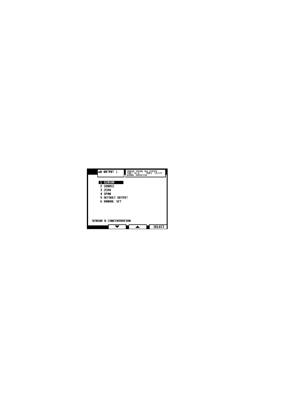
− Select the mA output, 1 or 2, to get to the Output menu (Figure 6.10 below)
where the output can be configured.
Note: The line at the bottom of the Output menu display indicates the current
configuration of the selected mA output, e.g. in Figure 6.10 mA Output 1 has
been configured to send the concentration reading of Sensor B.
Figure 6.10
The Output menu for mA Output 1
− To change the sensor the selected output is assigned to, select
1 SENSOR
in the
Output menu.
− To change output source for the selected output, select
2 SOURCE
.
Note: Selecting
1 NOT DEFINED
’turns off’ the selected output.
− The
3 ZERO
value sets the value when the signal is 4 mA. The default zero value
is 0.00, the unit depends on the source and display unit set for the sensor in
question (and can thus be for example 0 BRIX or 0 °F).
− The
4 SPAN
sets the range, i.e. the value given when the signal is 20 mA.
Example: If your measurement unit is CONC% and you want to measure the range
15–25 CONC%, first choose concentration as mA output source. Then set the zero
value at 15 and span at 10. This means that the output signal is 4 mA at 15 CONC%
and 20 mA at 15+10=25 CONC%. To change this output to range 10–30 CONC%,
change zero to 10 and span to 20 (10+20=30).
−
5 DEFAULT OUTPUT
sets a mA default output value that the instrument returns to in
certain malfunction situations. The value can be set to a low or high mA value,
e.g. 3.0 mA or 22 mA. For a list of malfunctions that are affected, see section 8.4.