Isolator unit, 3 isolator/barriers – K-Patents PR-21-S User Manual
Page 108
102
PR-21-S instruction manual
Cables:
− 10 m (33 ft) cable, part number PR-8230-010, connecting the Indicating trans-
mitter STR and the Isolator unit.
The maximum cable length is 100 m (330 ft).
− 10 m (33 ft) power cable, part number PR-8250-010, connecting the Indicating
transmitter STR and the Isolator unit, part number PR-8250-010. The maxi-
mum length is 100 m (330 ft).
− The intrinsically safe cable between Isolator unit and sensor, part RP-8260-xxx,
where xxx is the cable length in meters. The maximum length is 100 m (330 ft).
For cable connections see Figures 10.15 and 10.16.
Note: Isolator/Barrier Unit can also use an optional external +24V DC power sup-
ply instead of the +24V DC power supply from the transmitter. +24V DC is con-
nected to terminals 13 and 14. (If +24V DC is used, the PR-8250 power cable is
not used at all.)
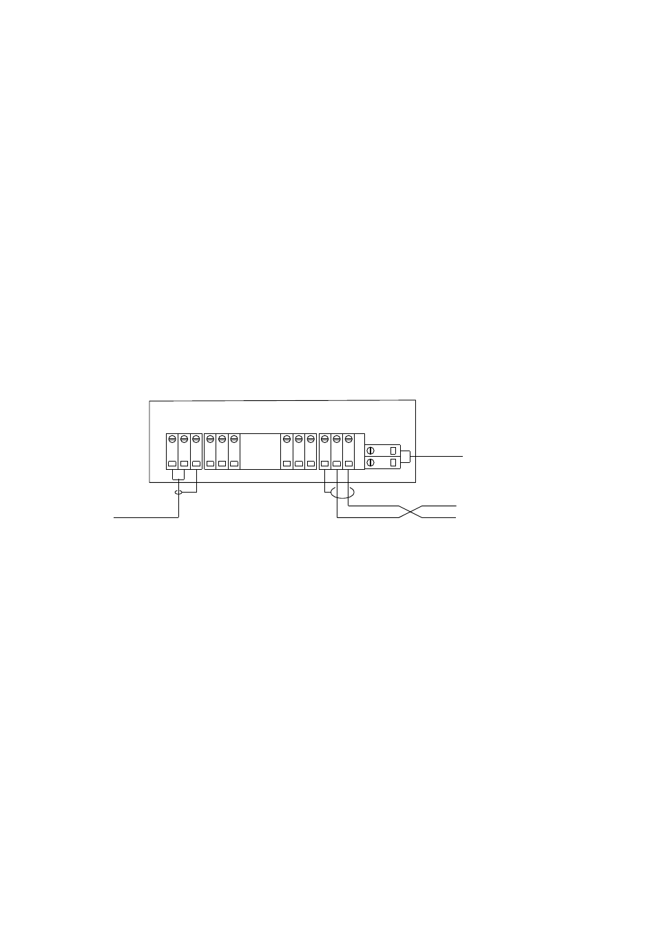
10.5.3 Isolator/barriers
Isolator unit wiring is explained below in Figure 10.16.
2
1
3
5
4
6
8
7
9
11
10
12
1
3
1
4
+ve
-ve
+ve
-ve
-vs
+vs
ISOLATOR UNIT
24VDC
Power cable
PR-8250-xxx
(max 100m)
(max 100m)
(max 200m)
Cable
PR-8230-xxx
1
2
Cable
PR-8260-xxx
Figure 10.16
Isolator unit wiring
Note: If the power to Isolator unit terminals is not correctly connected, +24V DC
to terminal 14 (+vs) and zero to terminal 13 (-vs), the transmitter STR will give the
message
No signal
. Also if terminals 11 and 12 are not correctly connected, sensor
cable connecting terminal 2 of the Indicating transmitter STR to the Isolator unit
terminal 11 (-ve) and terminal 1 of the STR to Isolator unit terminal 12 (+ve) , the
message
No signal
will appear.