K-Patents PR-21-S User Manual
Page 57
6 Configuration and calibration
51
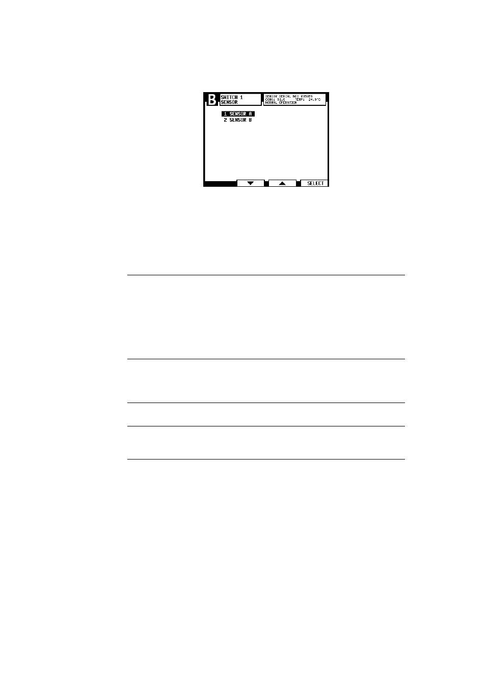
Figure 6.9
Arrival to Switch 1’s sensor selection menu, sensor A selected
6. In the Switch menu, select
2 FUNCTION
to set switch function.
Note:
The current assignment of the switch is shown at the bottom of the
Switch menu display, e.g. Figure 6.9 Switch 1 is assigned to Sensor A with func-
tion Wash stop.
1
NOT DEFINED
Factory setting
2
HOLD
When used with a built-in wash relay, this func-
tion is useful for an intermittent process: the prism
is washed when the process stops (as indicated by
contact closure). The wash is repeated when the
process restarts (if the stop lasts over 60 seconds).
The signal is on hold between washes. When used
with an external independent timer, contact closure
holds the output signal.
3
WASH STOP
Switch closure prevents wash cycle. It can be used to
prevent wash action when the process pipe is empty.
The message
WASH STOP
will appear when a wash cycle
is initiated.
4
REMOTE WASH
At switch closure the system waits for an external
wash command before initiating wash.
5
SCALE SELECT
Any chemical curve and associated field calibration
scale can be selected by switch closure. The scales
assigned to each switch independently.
6
CALIBRATION SEAL
Contact closure prevents access to calibration and
configuration ("external password"). Can be used to
seal the calibration.
7. If you chose Scale select as switch function, return to the Switch menu (if not
returned automatically) and choose
3 SCALE CHEMICAL
to enter the parameters for
the chemical curve assigned to the switch. See Section 6.6.1 for more informa-
tion on chemical curves and chemical curve parameters.
8. If necessary, the chemical curve assigned to a switch can be adjusted by field
calibration parameters. Select
4 SCALE FIELD
in the Switch menu to enter the pa-
rameters. See Section 6.6.3 for more information on field calibration and field
calibration parameters.