Power supply connections (cont.), Installation, Warning – Hypertherm HT4001 Plasma Arc Cutting System User Manual
Page 65
INSTALLATION
5-00
4-12
HT4001
Instruction Manual
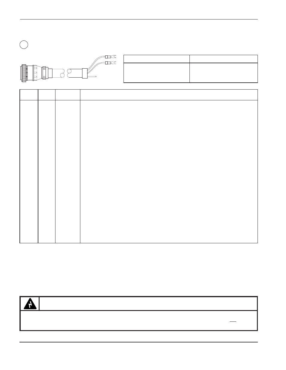
Power Supply Connections (cont.)
Machine Interface I/O Cable – PS to Machine Interface
PS END
MACH. END
SCKT
COLOR
LUG
DESCRIPTION AND COMMENTS
1
Wht
87
Hold (12VDC) Signal. Synchronizes starting of 2 or more systems. Closed=ON; Open=OFF
5
Blk
86
Hold - Common
10
Shield
Cut
Hold - Shield
2
Yel
173
Initial Height (12VDC) Signal. Closed=OFF ; Open=ON
6
Blk
174
Initial Height - Common
11
Shield
Cut
Initial Height - Shield.
3
Brn
171
Auto Height (12VDC) Signal. Closed=OFF; Open=ON or Corner (12VDC)
7
Blk
172
Auto Height - Common
12
Shield
Cut
Auto Height - Shield
4
Orange
135
Remote On/Off - See note on next page
8
Black
136
Remote On/Off - See note on next page
13
Shield
Cut
Remote On/Off - Shield
9
Blu
82
Plasma Start (24VAC) - Signal. Close=Start
15
Blk
83
Plasma Start - Signal.
14
Shield
Cut
Plasma Start - Shield.
22
Red
77
Upper Limit Switch, Hot. Normally closed. Open when fully retracted.
21
Wht
76
Upper Limit Switch, Neutral.
20
Shield
Cut
Upper Limit Switch, Shield.
28
Yel
80
Plasma Emergency Stop (24VAC) Signal. Closed =stop.
33
Red
81
Plasma Emergency Stop - Signal
27
Shield
Cut
Plasma Emergency Stop - Shld
34
Red
169
∞
†Down Relay, Load (Solid state, rated to switch 24 to 120VAC, 1amp. DC relay optional) Closed=Down
29
Blk
170
Down Relay, Line
23
Shield
Cut
Down Relay, Shield
35
Grn
167
∞
†Up Relay, Load (Solid state, rated to switch 24 to 120VAC, 1amp. DC relay optional) Closed=Up
30
Blk
168
Up Relay, Line
24
Shield
Cut
Up Relay, Shield
36
Red
84
†*Arc Xfer Output - Signal Contact closes after arc transfer and time delay. Dry contact relay.
31
Blu
85
*Arc Xfer Output - Signal
25
Shield
Cut
*Arc Xfer Output - Shield
37
Red
79
**Arc Voltage Isolated + Divided (1/100) Signal
32
Grn
78
**Arc Voltage Isolated + Divided (1/100) Sig
26
Shield
**Arc Voltage Isolated + Divided (1/100),Shld
7
PS End
Notes:
* Note on the µP PCB that resistor R150 and capacitor C78 are connected in series across the contacts. In some cases one lead of
R150 must be cut from the control PC board as the R-C circuit may provide enough current flow to maintain machine motion input to
cutting machine.
** Note on the µP PCB that resistor R155 and capacitor C79 are connected in series across the contacts. In some cases one lead of
R155 must be cut from the control PC board as the R-C circuit may provide enough current flow to maintain machine motion input to
cutting machine.
∞
Signals are AC relays. DC relays are available as an option from Hypertherm by ordering kit: 128404
1X6
†
WARNING
When installing or servicing the HT4001, AC or DC line voltages may be present on the UP, DOWN and
TRANSFER signals even if the power supply line disconnect switch is OFF. Make certain that all line
disconnect switches relating to the HT4001 system are OFF during installation and when servicing.
Part No.
Length
023892
25 ft (7.5 m)
023893
50 ft (15 m)
023894
75 ft (23 m)
Part No.
Length
023895
100 ft (30.5 m)
023896
150 ft (46 m)
023897
200 ft (61 m)