Power supply connections -6, Power supply connections – Hypertherm HT4001 Plasma Arc Cutting System User Manual
Page 59
INSTALLATION
4-97
4-6
HT4001
Instruction Manual
Part No.
Length
023136
20 ft (6 m)
023078
25 ft (7.5 m)
023101
30 ft (9 m)
023135
40 ft (12 m)
023079
50 ft (15 m)
Part No.
Length
023124
75 ft (23 m)
023080
100 ft (30.5 m)
023081
150 ft (46 m)
023316
180 ft (55 m)
023188
200 ft (61 m)
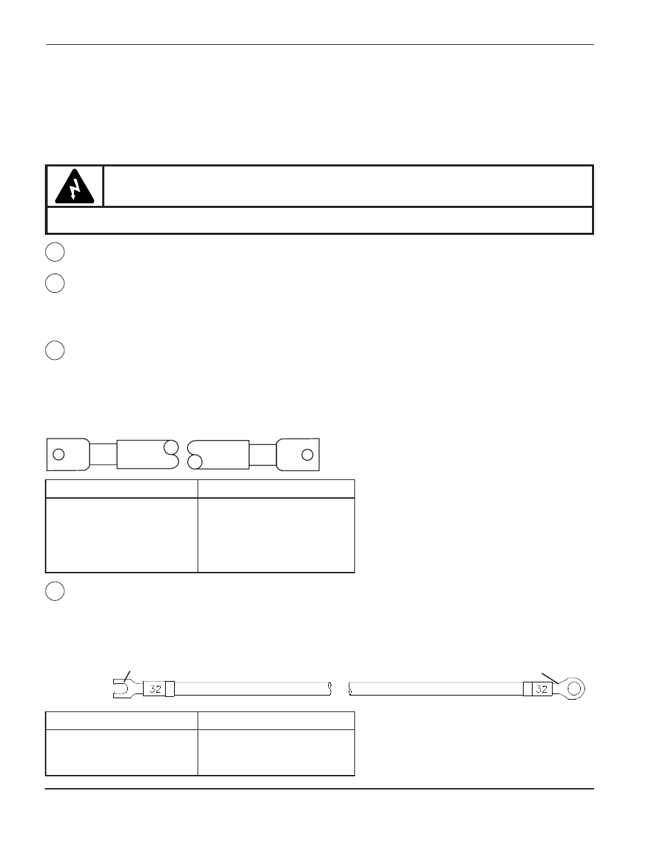
Nozzle Lead – PS to RHF Console
Pass the fork terminal end of the nozzle lead through the small bushing in the lower rear of the HT4001 power
supply and connect to the start circuit assembly as shown in Figure 4-4. Connect the ring terminal end of the
nozzle lead to the inductor coil in the RHF console. See pages 4-8 and 4-22 through 4-25 for remaining RHF
console connections.
Power Supply Connections
The circled numbers on the right-hand pages represent connection points for the corresponding numbered cables
and hoses on the left-hand pages. Any special instructions for installation are also explained on the left-hand
pages. The cable and hose part numbers in this section represent the most commonly used lengths. For
additional lengths, see Section 7 or call Hypertherm.
Part No.
Length
123009
25 ft (7.5 m)
123010
50 ft (15 m)
123011
75 ft (23 m)
Part No.
Length
123012
100 ft (30.5 m)
123013
150 ft (46 m)
123014
200 ft (61 m)
1
2
3
4
Fork Terminal
Ring Terminal
Power Cables – Power Supply (PS) to Power Source
See Connecting the Power in the Pre-Installation section of this manual.
Negative Lead – PS to Remote High Frequency (RHF) Console
Pass the negative 2 lead through one of the 2" bushings in the lower rear of the HT4001 power supply and
connect to the lower bar (-) on the center bail rear as shown in Fig. 4-4. Connect the other end of the negative
lead securely to the cathode block in the RHF console. See part number information below under Positive
Lead – PS to Work Table
Positive Lead – PS to Work Table
Pass the positive 3 lead through one of the 2" bushings in the lower rear of the HT4001 power supply and
connect to the upper bar (+) on the center bail rear as shown in Fig. 4-4. Connect the other end of the lead
securely to the grounded work table.
Note:
Two positive and two negative leads needed when cutting with from 400-750 amps. See
Appendix A to connect H401 Slave to HT4001 power supply.
WARNING
All power must be turned OFF before performing installation!!