3 preliminary specifications – FSR RN-8200 User Manual
Page 6
1.0 General Information
RN-8200 Reference Manual
Page 1-2
1.1.3 Preliminary
Specifications
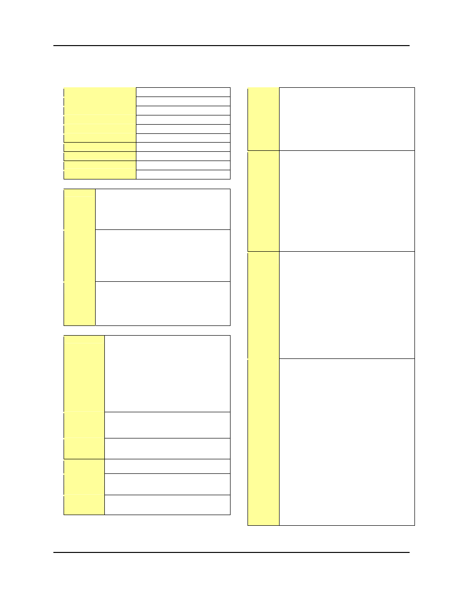
General
Power
100 – 240 VAC, 43-65 Hz, 25 Watts
Temperature / Humidity
Enclosure Type
Metal
Enclosure Dimensions
Product Weight
Shipping Weight
DIM Weight
Approval Listings
UL
MTBF
30,000 hours
Warranty
Audio
Audio
Frequency Response: 20 Hz to 20 KHz
Gain: .+6dB
THD + Noise: .
<0.15%
Crosstalk: .
>90dB
Stereo Channel Separation:
> 100dB @ 1KHz
PSRR: 90dB
Video
Inputs
Number of Inputs / type:
8 stereo or mono, balanced or unbalanced
Connectors: Pluggable screw terminals
Impedance: 10 KOhms, unbalanced
Nominal Level: 0.775 V
Maximum Level: .5.0V
Input Gain adjustment: .-45 dB to +5 dB
Input Trim adjustment: .-5 to +15 dB
Audio
Outputs
Number/ signal type:
1 Stereo or mono, balanced or unbalanced
Connectors: Pluggable screw terminal
Impedance: 50 Ohms designed to drive
600-Ohm load
Nominal level: +6 dBu
Maximum level: +22 dBu
Control
Serial Control Serial Control Ports: 6 total
(4) RS-232 ports w/ 3 pole captive screw
connectors:
– Pin 1 = Tx,
– Pin 2 = Rx,
– Pin 3 = Gnd
(1) RS232 serial port, w/ 9-pin Sub D female
connector
– Supports remote control from PC (or
similar), configuration from PC
– Can be used a fifth device control port
(1) RS-485 serial port for remote wall panel
control
LAN Interface
1 RJ-45 female Ethernet control port
Ethernet Data Rate: 10/100 BaseT
Protocols: TCP/IP, SMTP, ARP, DHCP, HTTP,
ICMP, Telnet
Relay Control
Number/Type: (4), 1 Amp Form A
Connectors: Pluggable, captive screw connectors
Connector rating: 200V, 0.5A, 10W
Remote Panel
Control I/F
5-Pole captive screw connector supporting a
dedicated RS485 serial connection
IR Remote
Control
Front panel IR learner: 40KHz center freq
(4) IR output ports
2 pole pluggable captive screw connectors
Program
Control
Window’s
® based Configuration Utility
Web Browser for control via embedded web server
Virtual Control Panel
Video
Video
Bandwidth: 275 MHz (+/- 3dB), fully loaded
Gain: Unity
Flatness:
RGB +/- 0.5dB to 182MHz
Crosstalk:
RGB: -45dB @ 5MHz
S-video and Composite video:
–52 dB @ 10 MHz
Differential Phase Error:
< 0.1°
Differential Gain Error:
< 0.1%
Sync
Input Type: RGBHV
Output Type: RGBHV
Standards:
TTL (RGB),
NTSC3.58,
NTSC 4.43,
PAL,
SECAM
Input level: 2.0 V TO 5.0V p-p
Output level: 5.0V p-p, un-terminated
Input impedance: 511 Ohms
Output impedance: 75 Ohms
Max. Input voltage: 5.0V p-p
Max. Propagation delay: 48ns
Max. Rise/fall time: 6ns
Polarity: positive or negative depending on input
Video
Outputs
Type 1: RGBHV
Type 2: Composite Video
Type 3: S-Video
Impedance: 75 Ohms
Nominal Level:
RGB: 0.7V p-p
Y of S-Video and Composite Video: 1 V p-p
C of S-Video: 0.3Vp-p
Connectors:
RGBHV: (1) 15 pin sub_D
Composite Video: (1) Female BNC
S-Video: (2) Female BNC
Return loss:
RGB < -45dB@5MHz
Composite and S-video: < -25dB 0 to 10 MHz
DC offset: +/- 30 mV with input at 0 V offset
Video
Inputs
Inputs 1 – 4, Signal Type:
RGBHV, S-Video, or Composite Video
Inputs 4 – 8, Signal Type:
S-Video, Composite Video only
Nominal signal Levels:
RGBHV: 0.7V p-p
Y of S-Video and Composite Video: 1V p-p
C of S-Video: 0.3V p-p
Maximum levels:
RGB Analog: +/-1.3V p-p with no offset
S-video, composite video Analog:
+/-2.2 V p-p with no offset
Input Connectors:
1 – 4, RGBHV: Four, 15 Pin Female sub-D
4 – 8, has both:
– S-Video: Four, 4 pin DIN, and
– Composite: Four, BNC Female
RGBHV Pin-Out:
RGBHV: Pin 1: R, Pin 2: G, Pin 3: B
S-Video: Luma (Y) Pin 2, Chroma (C) Pin3
Composite, CV Pin 1
Return Loss:
RGB: < -43dB@5MHz
S-Video: < -30dB 0 to 10 MHz
Composite video: < -30dB 0 to 10 MHz
DC offset (max allowable): +/- 1.5V
Input Impedance: 75 Ohms for all input types