FSR RN-8200 User Manual
Page 10
2.0 Installation and Operation Overview
RN-8200 Reference Manual
Page 2-2
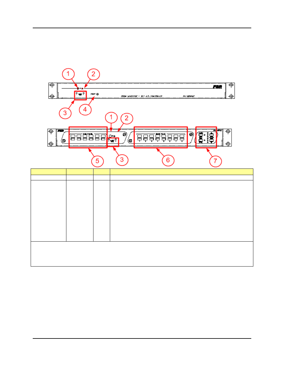
3) Audio Input Trim Up/Down Buttons
4) Power On Indicator (Blank Front-Panel Only)
5) Room Control Buttons (Standard Front-Panel Only)
6) Source Select Buttons (Standard Front-Panel Only)
7) Audio Control and Projector Mute Buttons/Indicators (Standard Front-Panel Only)
Indicator
Label
Color
Purpose and Operation
Power On LED
POWER
Green
On steady whenever power is applied
Status LED
IR
Red
This indicator LED serves as a communication status and normal processing status
indicator. It comes on at times to indicate operations are occurring. Specific
indications provided by this indicator are as follows:
Each time an incoming data byte is received from Serial Port 1, the light comes
on momentarily as the byte is moved into the incoming data buffer. This flash
is usually not noticeable because it happens so fast.
Comes on whenever one or more commands are processed; the commands
could be a result of button presses, or from data coming in via serial port 1.
Comes on during IR Learn command to tell the user the learner is ready and
waiting for the IR signal.
Flashes at power-up to indicate the current Port 1 baud rate setting:
1 = 1200 2 = 2400 3 = 4800 4 = 9600
5 = 19200 6 = 28800 7 = 38400 8 = 57600
Note:
If upon power-up, the Status LED is on steady, it means the RN was left in FW Update Mode. This is an
unusual condition but can occur if a FW update was interrupted by a power outage or other unexpected condition.
If this occurs, the CU will recognize this condition and allow you to either return to normal mode or execute a
complete FW update before returning to normal mode.