2 cabling considerations – FSR RN-8200 User Manual
Page 11
2.0 Installation and Operation Overview
RN-8200 Reference Manual
Page 2-3
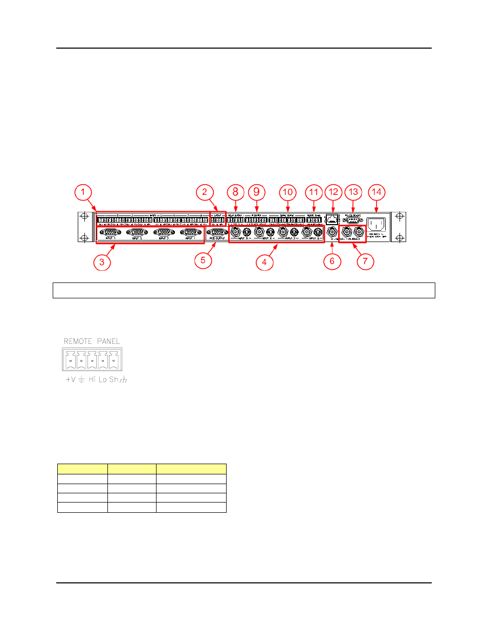
2.1.1.2 Rear Panel
The rear panel is shown below. Features of this panel are as follows:
1) Audio Inputs (1 through 8)
2) Audio
Output
3) Video Inputs (1 through 4)
4) Video Inputs (5 through 8)
5) RGB Video Output
6) Composite Video Output
7) S-Video
Output
8) Relay Control Ports (1 through 4)
9) IR Control Ports (1 through 4)
10) Serial (RS-232) Control Ports (1 through 4)
11) Remote Panel Interface (RS-485)
12) LAN Interface (RJ45)
13) RS-232 Remote Control Interface
(or serial control port 0)
14) AC Power Input
2.2 Cabling
Considerations
2.2.1 RS-485 Remote Control Panel Port (WallPlate Interface)
Pinout
The RN-8200 has a five pin pluggable screw connectors for wiring the Remote Panel(s)
to the Rack Unit. The cable types and limitations are detailed in the chart below.
The RN Rack unit can support up to 8 Remote Panel’s daisy-chained on its remote panel
interface. The Rack Unit’s internal power supply can directly support three control panels.
Additional Remote Panels require a separate power supply. The front panel on the rack
unit counts as one panel and has the reserved address of “0”. Each remote panel has a
dipswitch for setting its unique ID (0 through 7).
Note: If more than 2 wallplates are required for an installation, an additional external
power supply is required to supply current to the wallplates. The last Remote
Panel in the chain should have Dipswitch 1 placed in the up position. A “daisy
chained wiring configuration is preferred over a “star” for Remote Panel wiring
(see section 2.2.1.1 below).
Recommended Cable Type: Two twisted pair with an overall shield or CAT5 per table below
# Wallplates
Wire Gauge Max Cable Length
1
22 *
450 ft
1 18 1200
ft
2
22 *
350 ft
2 18 900
ft
* CAT5 cable (24ga., 4 pair) may be used:
one pair for “V+”,
one pair for ground return,
one pair for data and one pair for shield.