1 serial port communication data formats, 2 serial port communication flow control – FSR RN-8200 User Manual
Page 29
3.0 Configuration Utility Software
RN-8200 Reference Manual
Page 3-8
3.2.6.1.1
Serial Port Communication Data Formats
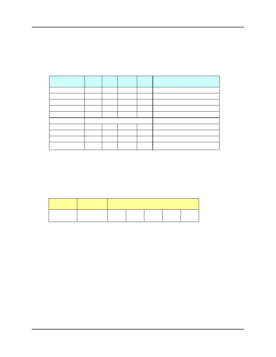
The RN supports several common data formats for the number of data bits and parity. One Start bit and one Stop
bit are always used. The supported data formats combined with selectable baud rate and flow control make the RN
capable of supporting the vast majority of devices that may be encountered. The BAUD SET command is used to
configure the serial ports to the desired format including the desired baud rate and flow control. The table below
identifies the communication format options available
.
3.2.6.1.2
Serial Port Communication Flow Control
The serial control ports use the most common and easiest interface of only 3 wires (RX, TX and GND). The remote
RS-232 host port use a DB9 interface and supports user selectable hardware flow control (RTS, CTS). The table
below provides a summary of the Remote RS-232 DB9 connector interface on the Room Navigator.
Equipment
Type
DB9
Connector
Pin Assignments
DCE
RTS = INPUT
CTS = OUTPUT
Female CTS
(8)
RTS
(7)
TD
(2)
RD
(3)
GND
(5)
The RN uses a common form of hardware handshaking supported by most RS232 interfaces where each end has a
handshake output signal and the receiver brings its handshaking output signal high when it’s ready to receive data.
The transmitter must monitor this signal and ensure it is high before each transmission. For example, when using
hardware handshaking, a computer, being a DTE device, uses RTS to indicate when it is ready to receive data.
Similarly, the computer monitors the CTS from the RN to know when the RN is ready to receive data. When
connected to a computer, and using hardware handshaking, the RN uses the computer’s RTS signal so that it knows
when the computer is ready for data. Similarly, the RN uses its CTS signal to tell the computer when it is ready for
data.
3.2.6.3 Serial Port Echo Modes
Echo Mode is a parameter associated with each serial port and it provides a means to relay information from the
host port to a device or monitor serial feedback from devices. For example, a PC-based host application may want
to get bulb usage from a projector and in order to do so; it must be able to pass data from the serial control port back
to the host connected to the host port. Therefore a serial control command to the appropriate serial control port with
Echo Mode turned ON for that control port, will achieve this “echoing” of the feedback to the host. For all 4 serial
control ports, the echo modes are either On or Off.
Format
Start
Bits
Data
Bits
Parity
Stop
Bits
Comments
8N1 1
8
None
1
Factory
Default
8E1 1
8
Even
1
8O1 1
8
Odd
1
8M1
1
8
Mark
1
Parity bit always “1”
8S1
1
8
Space
1
Parity bit always “0”
7N1
NOT USABLE
7 Data bits only valid with a parity bit
7E1 1
7
Even
1
7O1 1
7
Odd
1
7M1
1
7
Mark
1
Parity bit always “1”
7S1
1
7
Space
1
Parity bit always “0”