FSR RN-8200 User Manual
Page 28
3.0 Configuration Utility Software
RN-8200 Reference Manual
Page 3-7
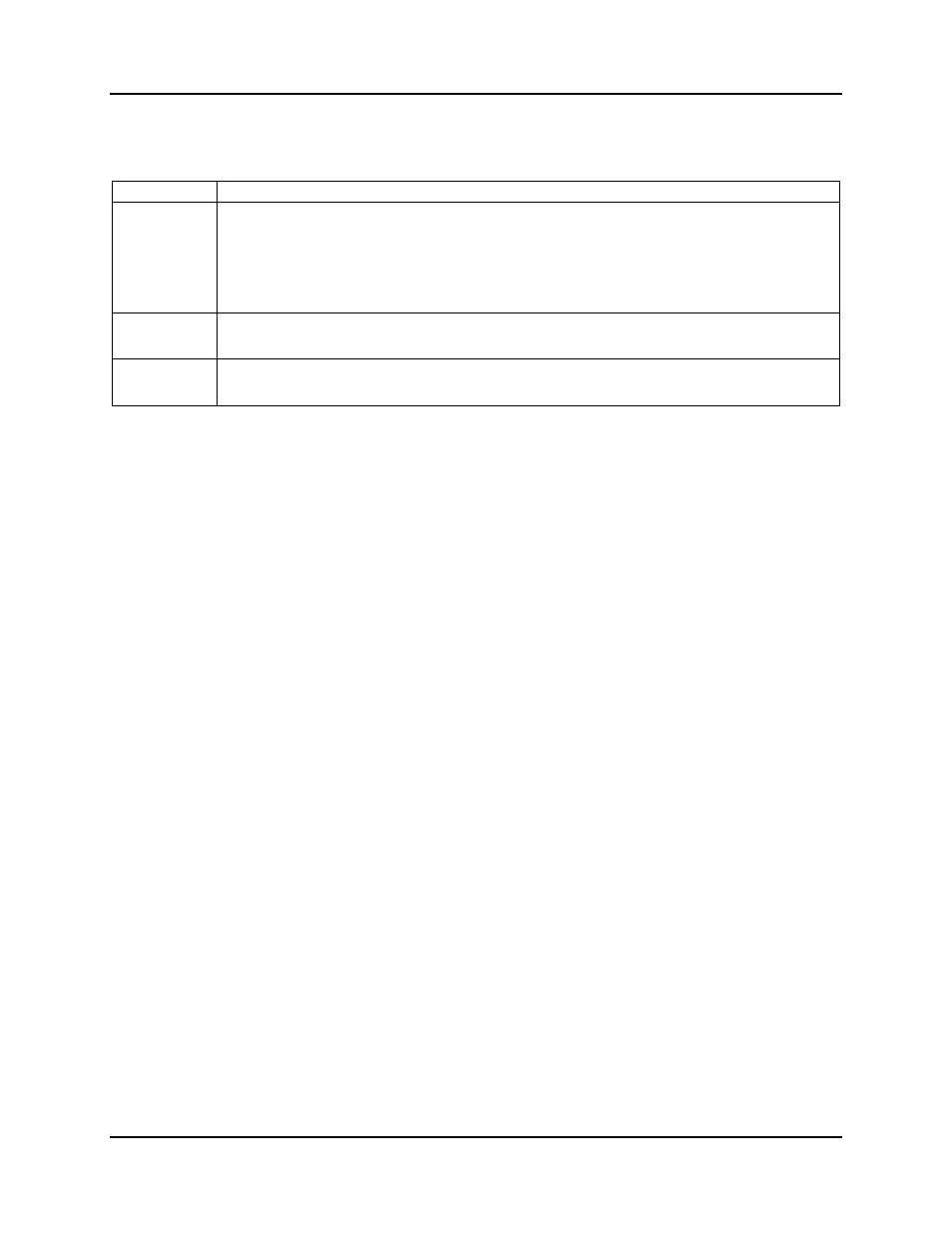
also a “PC Port” drop-down item to allow selection or change of the PC COM port being used. The remaining
parameters are described in the table below.
ITEM DESCRIPTION
Echo Mode
This item designates a destination port to which all incoming data will be echoed meaning it will be transmitted
out that port. When Echo Mode is off, the incoming data is not echoed to another port.
Example 1: If Port 1 Echo Mode is set to “Port 2”, all data received on Port 1 will be echoed to Port 2
meaning it will be transmitted out Port 2.
Example 2: If Port 2 Echo Mode is set to “Port 1”, then all incoming data on Port 2 will be echoed to Port
1. Echoing port 2, 3, or 4 to Port 1 allows you to direct device responses to commands back to a
controlling host connected to Port 1.
Transfer Delay
The Transfer Delay is provided as a means to interact with some old equipment that cannot process standard
RS-232 data streams without providing the delay between bytes. These old systems are not common and
unless you know you need the delay, this value should always be 00 to ensure best performance.
Address Setting
Allows you to assign a unique Device ID to the Room Navigator. This can be useful when multiple Room
Navigator units are daisy-chained together. The Device ID can be used in any command to specifically target
one or more, but not all, Room Navigator devices in the chain.
3.2.6.1 Device Addresses
The RN is addressable so that it may be daisy-chained with other FSR control devices. The device comes from the
factory with the default address of “00”. Valid addresses are 00-99. Device addresses are an optional element of
each command sent to the device or to a chain of devices. When no device address is used, the command is a “wild
card” and all connected devices will accept and execute the command.
When only one device is connected, no device addressing is necessary and all commands can be sent as wild card
commands. When more than one device will be connected, it is recommended that the devices are programmed one
at a time and addresses are assigned starting at “01”. Up to 100 devices may be daisy-chained using addressing
“00” through “99”.
3.2.6.2 Serial Ports
The RN has 5 RS-232 serial ports; 1 is for remote control and uses a DB9F interface and the other 4 are for device
control and they use a 3-wire Phoenix-Style connector interface. During operation, all 5 RS-232 ports can be
separately used to control devices in that serial control strings can be designated to be transmitted out to these ports
when buttons are pressed or via remote commands received from the Remote RS-232 port.
The remote RS-232 port is also designated as the programming port and only this port can be used to configure
(using the CU). This port can also be used to remotely control the RN from a remote control host device or a PC
running a control application. Unlike the 4 serial device control ports, all data received on the remote RS-232 port
is processed by the RN and any data sequences that match the valid commands of the RN command set will be
processed accordingly. Therefore, always use the remote RS-232 port as the connection to a remote controlling
device. A remote controlling device is considered any device intended to send commands to the RN or intended to
send commands through the RN to a device that may connected to one of the other serial ports.