FSR RN-8200 User Manual
Page 15
2.0 Installation and Operation Overview
RN-8200 Reference Manual
Page 2-7
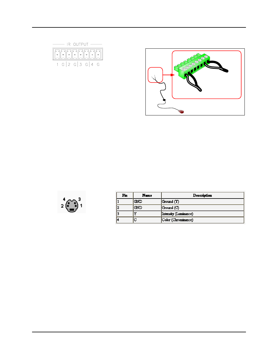
2.2.6 IR Control Ports
The RN has 4 IR control ports and comes with 2 IR
emitters. Each emitter has two wires. The white stripe is
the positive lead and it goes on the right when looking into
the wire end of the connector. At the IR port, the white
stripe connects to the pin labeled 1, 2, 3, or 4, depending
on the port you wish to use. When you connect the
emitter to the equipment, be sure to center it over the IR
receiver as closely as possible. If you are having trouble
locating the IR receiver, try using a small flashlight to
illuminate the inside of the equipment panel as this can
sometimes allow you to see the receiver location clearly.
IR Emitter
1
IR
Port 1
IR
Port 4
4
G
G
Ports 1 and 4 shown wired.
2.2.6.1 IR Power Adjustment
The IR power output can be adjusted using trim pots located inside the unit. This adjustment capability is provided
accommodate the occasional piece of equipment that may require a higher power IR signal (or lower power). For
most equipment, the power can be left centered (factory default position). The four adjustment pots are located
inside the rear panel approximately behind the IR output ports. Trim pot 1 is for IR port 1 and so on. To increase
the power, you decrease the output resistance by turning the adjustment counter-clockwise. To decrease the power,
turn the adjustment clockwise.
2.2.7 S-Video Input Connector Cabling
Cable Type: Standard 4 pin S-Video to
two BNC male cable.
Maximum Recommended Length: 35 ft
Pinout
2.2.8 Composite Video Inputs and Outputs Connector Cabling
Use standard 75 ohm BNC cable for all composite video inputs and outputs.