Slot 1 – analog output block, Slot 2 through 5 – discrete input block, Slot 6 and 7 – discrete output block – Flowserve MX/QX Profibus DP/PA Field Unit User Manual
Page 74: Slot 8 – analog input block
PB DPV1 / PA Field Unit Installation and Maintenance FCD LMENIM2336-03 – 12/12
74
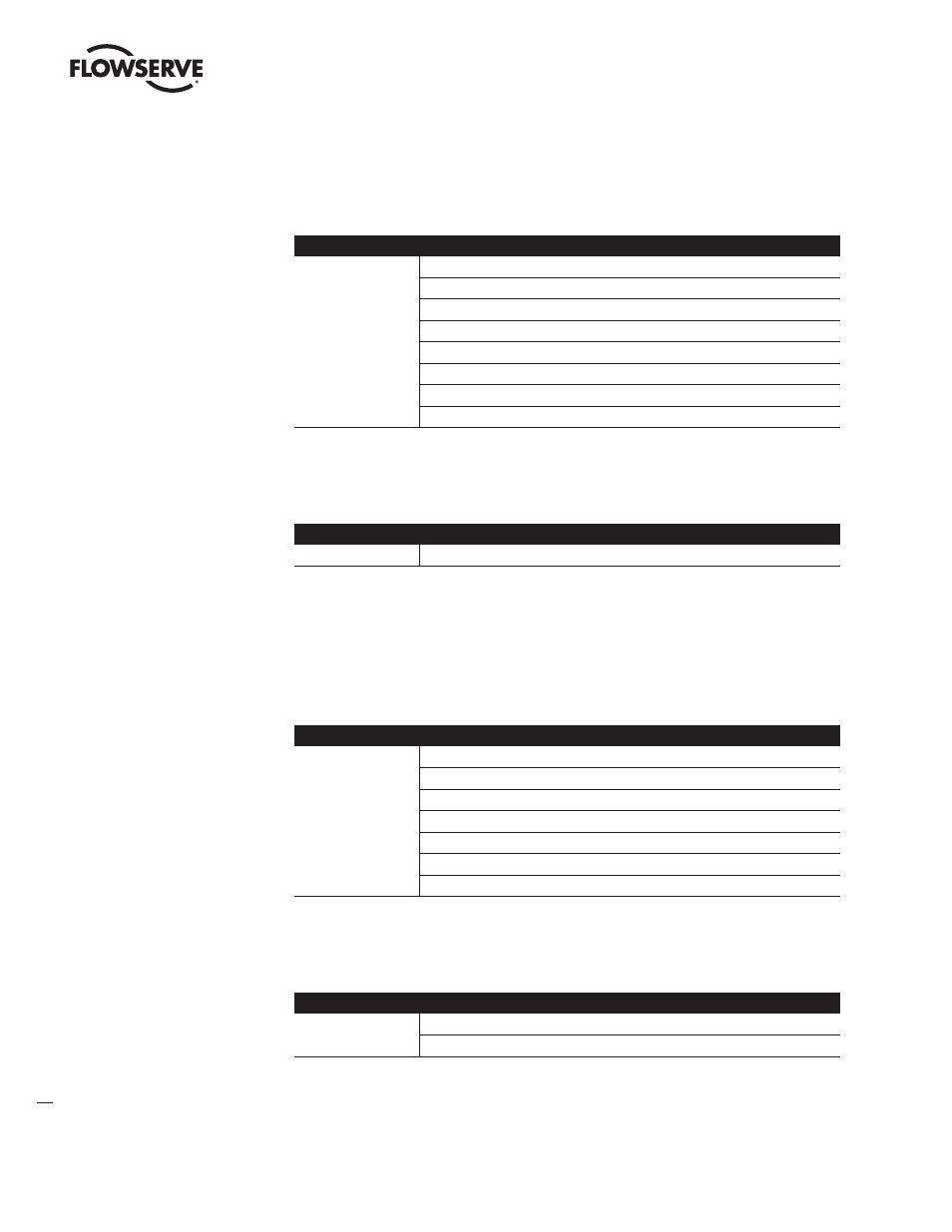
Slot 1 – Analog Output Block
There are eight possible module configurations that can be inserted into this slot:
Parameter Key: (RIN = RCAS_IN, RB = READBACK, ROUT = RCAS_OUT, CB = CHECKBACK)
Slot 1 – Analog Output Block
Module
SP(short)
SP(long)
RCAS_IN + RCAS_OUT
SP + READBACK + POS_D
SP + CHECKBACK
SP + READBACK + POS_D + CHECKBACK
RCAS_IN + RCAS_OUT + CHECKBACK
SP + RIN + RB + ROUT + POS_D + CB
Slot 2 through 5 – Discrete Input Block
There is one possible module configuration that can be inserted into any of these four slots:
Slot 2 through 5 – Discrete Input Block
Module
OUT_D
Slot 6 and 7 – Discrete Output Block
There are seven possible module configurations that can be inserted into any of the two slots:
Parameter Key:
(RB_D = READBACK, CB_D = CHECKBACK, ROUT_D = RCAS_OUT_D, RIN_D = RCAS_IN_D)
Slot 6 and 7 – Discrete Output Block
Module
SP_D
SP_D + RB_D
SP_D + CB_D
SP_D + RB_D + CB_D
RIN_D + ROUT_D
RIN_D + ROUT_D + CB_D
SP_D + RB_D + RIN_D + ROUT_D + CB_D
Slot 8 – Analog Input Block
There are two possible module configurations that can be inserted into the slot:
Slot 8 – Analog Input Block
Module
OUT(short)
OUT(long)