Status bit definitions, Value & status – floating point structure, Coding of status – Flowserve MX/QX Profibus DP/PA Field Unit User Manual
Page 70
PB DPV1 / PA Field Unit Installation and Maintenance FCD LMENIM2336-03 – 12/12
70
Status Bit Definitions
Reprinted from “PROFIBUS-PA Profile for Process Control Devices, Version 3.0.”
© Copyright PNO e. V. 1999. All Rights Reserved.
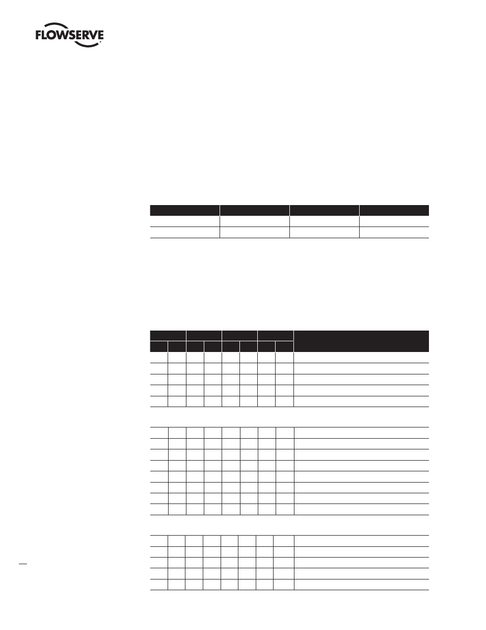
Value & Status – Floating Point Structure
This data structure consists of the values and the state of the Floating Point parameters. These
parameters can be inputs or outputs.
Data Type
Value & Status – Floating Point
Key Attribute
Index = 33
Attribute:
Number of Elements = 2
Attribute:
List of Elements (shown below)
E
Element Name
Data Type (Index)
Size
1
Value
Float - (8)
4
2
Status
Unsigned 8 - (5)
1
Coding of status
The definition of status attribute is the same for all parameters (input, output, and contained). There
are four states of quality of the data, an enumerated set of sixteen sub-status values for each quality,
and four states of limits placed on the data. Limit information is generated for all status attributes of
all parameters having status. Quality bit #7 and #6 (for cascade mode) must be set to “good” in the
second word of the data message while writing to AO and DO function blocks. See coding structure
below for details.
Quality
Quality
Substatus
Limits
Gr
Gr
QS
QS
QS
QS
Qu
Qu
2
7
2
6
2
5
2
4
2
3
2
2
2
1
2
0
0
0
= bad
0
1
= uncertain
1
0
= good (Not Cascade)
1
1
= good (Cascade)
Meaning at
= bad
0
0
0
0
0
0
= non-specific
0
0
0
0
0
1
= configuration error
0
0
0
0
1
0
= not connected
0
0
0
0
1
1
= device failure
0
0
0
1
0
0
= sensor failure
0
0
0
1
0
1
= no communication (last usable value)
0
0
0
1
1
0
= no communication (no usable value)
0
0
0
1
1
1
= out of service
Meaning at
= uncertain
0
1
0
0
0
0
= non-specific
0
1
0
0
0
1
= last usable value
0
1
0
0
1
0
= substitute-set
0
1
0
0
1
1
= initial value
0
1
0
1
0
0
= sensor conversion not accurate