Flowserve MX/QX Profibus DP/PA Field Unit User Manual
Page 18
PB DPV1 / PA Field Unit Installation and Maintenance FCD LMENIM2336-03 – 12/12
18
Table 2.4 – Recommended PROFIBUS DP Cable Types
FC Standard Cable (Siemens AG)
6XV1 830-0EH10
FRNC Cable (Siemens AG)
6XV1 830-0CH10
FC Food Cable (Siemens AG)
6XV1 830-0GH10
FC Ground Cable (Siemens AG)
6XV1 830-3FH10
FC Trailing Cable (Siemens AG)
6XV1 830-3EH10
Festoon Cable (Siemens AG)
6XV1 830-3GH10
PROFIBUS Data Cable (Belden Wire and Cable)
3079A/3076F
PROFIBUS DP Cable (Moeller GmbH)
ZB4-900-KB1
PROFIBUS DP Cable (Kerpenwerk GmbH)
7422/7436
PROFIBUS DP Cable (ABB Automation GmbH)
NDC110-NO
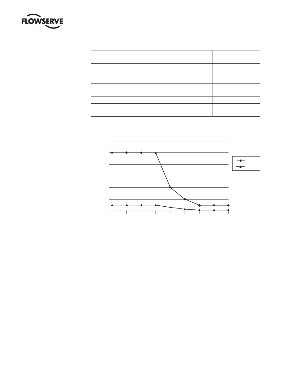
Figure 2.5 – Copper PROFIBUS Distance vs. Baud Rate Chart
12,000
10,000
8,000
6,000
4,000
2,000
0
9.6
1,500
3,000
12,000
Distance (m)
Baud Rate (kBaud)
Network
Segment
19.2
93.75
187.5
500
6,000
1,000
1,000
1,000
1,000
1,000
1,000
100
100
200
400
100
There are several topologies available for both redundant and non-redundant PROFIBUS networks:
• Point-to-point – A single cable from master to slave.
• Daisy chain – A single cable daisy chained in and out of each field unit device. End of segment
devices only have one incoming cable.
• Tree – Cables and electronic devices (such as repeaters or link modules) are used to branch out
from different points.
• Ring – Often implemented with fiber-optic cable which forms a circle or ring when used with
Optical Link Modules. This topology yields redundancy so that any single component fault or cable
break does not affect the network (except for the component).
• Combination of the above.
NOTE: Bus with Spurs, also referred to as stub lines, are not recommended by PROFIBUS as they can
create parallel resistance and cause disturbances and reflections on the main trunk or bus line.