2 network cable preparation, 1 network cable connection to the mx/qx pb unit – Flowserve MX/QX Profibus DP/PA Field Unit User Manual
Page 25
25
PB DPV1 / PA Field Unit Installation and Maintenance FCD LMENIM2336-03 – 12/12
flowserve.com
• A safety ground, free of ground loop currents, running from the actuator back to the system
ground electrode. If the signal wiring is run on aerial cable where it may be exposed to
high-energy electrostatic discharge (such as lightning), a low impedance path to ground which
is capable of high current must be provided a short distance from the actuator as described
above OR
• A power distribution grid identifying the impact of power isolation to a particular actuator or
group of actuators.
2.4.2 Network Cable Preparation
Care must be taken during cable preparation:
• When stripping the insulation, use wire strippers that do not nick the wire.
• Use crimp ferrules to prevent stranded wires from getting loose and shorting to other wires.
• Use vibration-resistant wiring terminals that hold the ferrule securely.
2.4.2.1 Network Cable Connection to the MX/QX PB Unit
The field device is connected to the PROFIBUS network through the MX/QX terminal block.
The PROFIBUS DP network cable is connected to the terminal block as shown in Figure 2.12.
NOTE: The MX/QX PB DP device is sensitive to polarity. Cable polarity should be maintained through
all connection points.
The PROFIBUS PA network cable is connected to the terminal block as shown in Figure 2.13.
NOTE: The MX/QX PB PA device is equipped with automatic polarity identification. It is not polarity
sensitive.
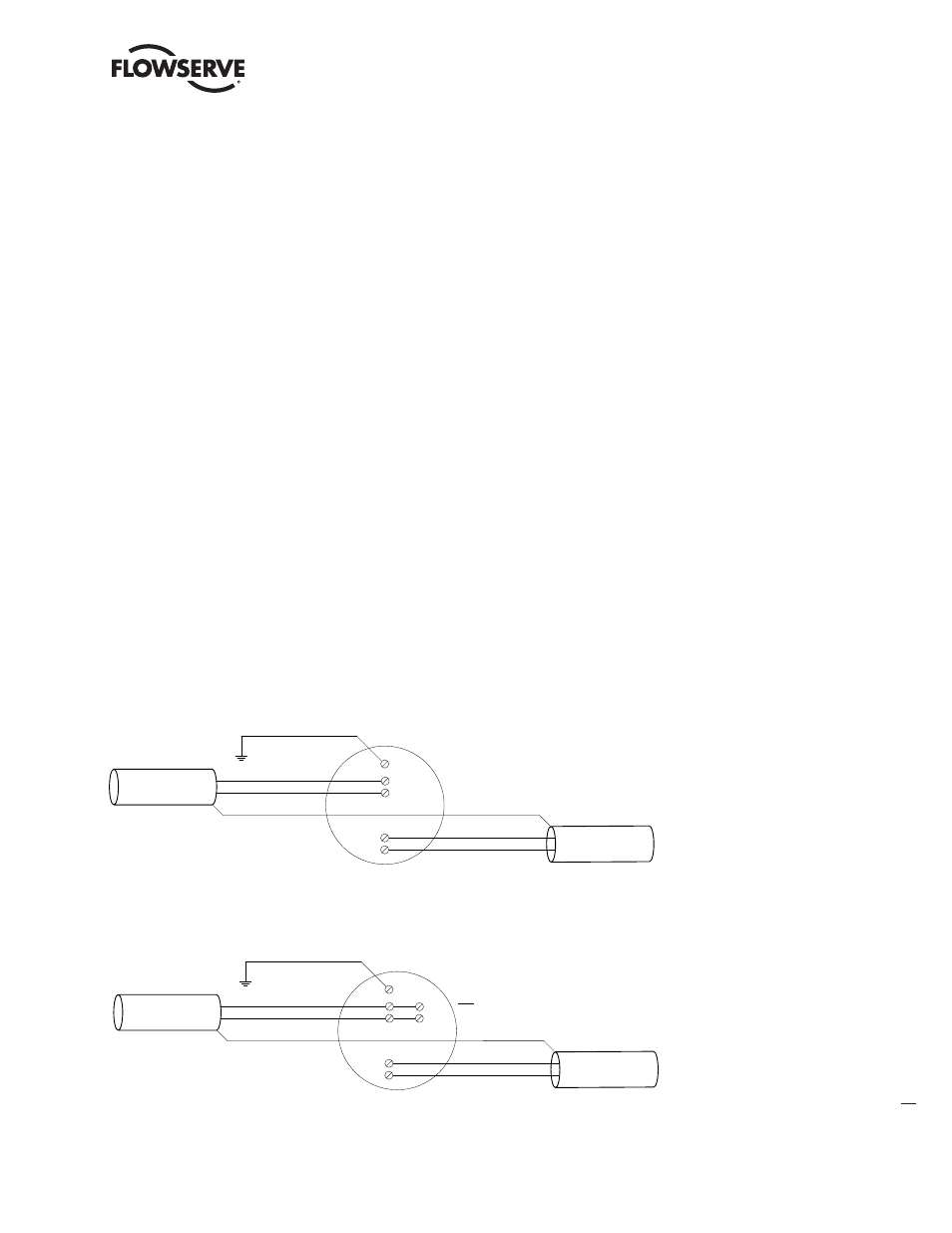
Figure 2.12a – PROFIBUS DP Cable Connections to Terminal Blocks
Figure 2.12b – PROFIBUS DP Cable Connections (Redundancy option with single master)
to Terminal Blocks
Earth ground
Figure 2.12(a) – PROFIBUS DP Cable Connections to Terminal Blocks
3
14
13
4
5
Network data PBDP-A (+)
Network data PBDP-A (-)
Network data PBDP-A (+)
IN
OUT
Network data PBDP-A (-)
Figure 2.12(b) – PROFIBUS DP Cable Connections (Redundancy option with single master) to Terminal Blocks
Note: External jumper connection required between
a) Terminals 14 & 15
b) Terminals 13 & 16
Earth ground
3
14
13
4
5
Network data PBDP-A (-)
Network data PBDP-A (+)
Network data PBDP-A (-)
Network data PBDP-A (+)
IN
OUT
15
16