Flowserve MX/QX Profibus DP/PA Field Unit User Manual
Page 39
39
PB DPV1 / PA Field Unit Installation and Maintenance FCD LMENIM2336-03 – 12/12
flowserve.com
The Transducer Block is used to convert signals from the actuator hardware to a digital format usable
by Function Blocks and the network host. It also conveys data from network users and Function
Blocks, sending this data to the actual hardware.
Function Blocks contains two types of parameters. The first type, Configuration parameters, are
used during commissioning to configure specifically what data the function block will use and how
it will process the data before sending it to its final destination. These configuration parameters are
sometimes called Acyclic parameters, because they are only read or written when needed.
The second type of parameter in a Function block is the Process parameter type. These parameters
provide the process data to the device or network user when the process is running. When the
process is running these parameters are updated in a periodic cyclic manner and are therefore
sometimes referred to as Cyclic data parameters.
The Function Blocks provide the network user with a standard interface for setting and obtaining
process data in the device. Function blocks can be connected together through the host to perform
the specific control functions of the process. The host device also monitors the function blocks to
supervise the entire control system.
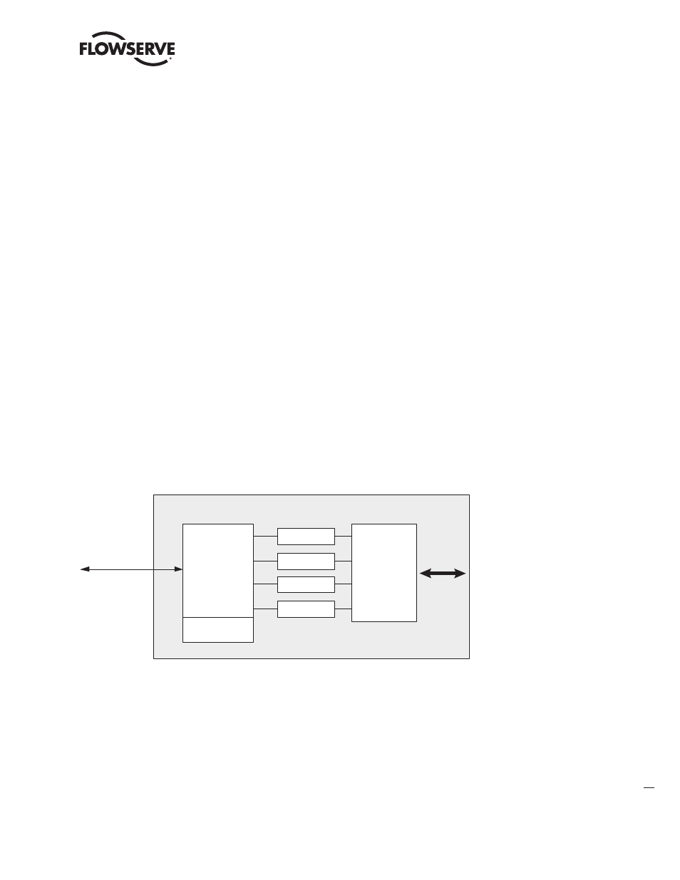
The figure below provides a block diagram view of the various standard “blocks” in the MX/QX
actuator for use by the network user.
The Analog Output and Discrete Output function blocks accept commands from the network user and
force the actuator to perform some kind of action, i.e., open, close, modulate, set network ESD, etc.
The Analog Input and Discrete Input bunction blocks provide the network user with information from
the actuator such as current position alarms, faults, etc. The following sections provide further details
about each function block.
Figure 3.1 – MX/QX Actuator Block Overview
Communication
Physical Block
One AI Blocks
Two DO Blocks
One AO Blocks
Four DI Blocks
MX/QX Actuator Block Overview
PROFIBUS
Networks
Actuator
Hardware
One
Transducer
Block