3 mx/qx pb device installation – Flowserve MX/QX Profibus DP/PA Field Unit User Manual
Page 30
PB DPV1 / PA Field Unit Installation and Maintenance FCD LMENIM2336-03 – 12/12
30
Figure 2.19 – Connecting Network Cable to the MX/QX Terminal Block
2.4.2.2 Network Cable Connection to the Host System
For instructions on connecting to the host system, see the applicable host system/station. There are
several topologies for the network detailed in Installation Guideline for PROFIBUS-DP/FMS, Version
1.0, September 1998 and PROFIBUS PA User and Installation Guideline, Version 2.2, February 2003.
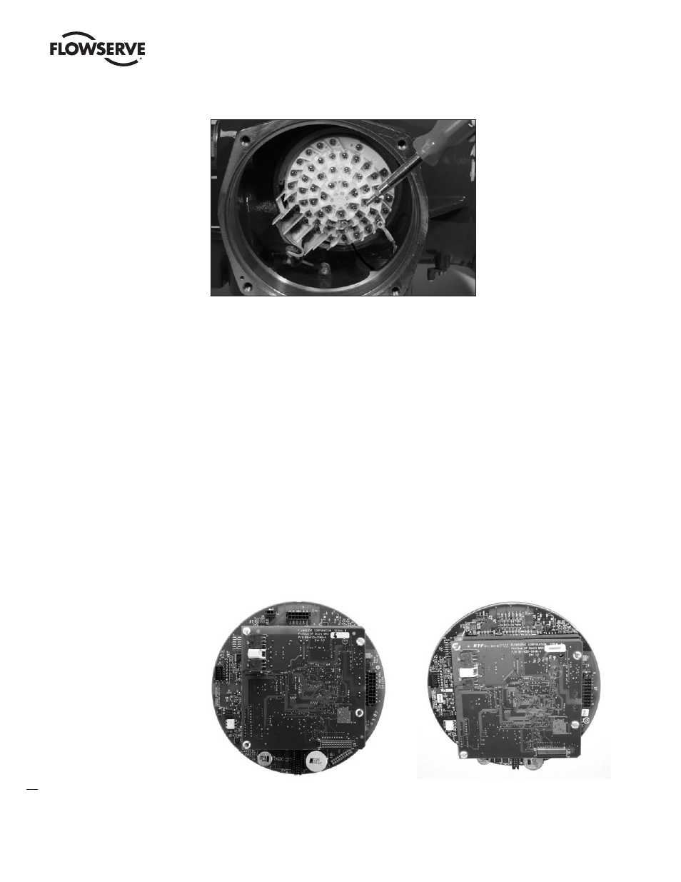
2.4.3 MX/QX PB Device Installation
The MX/QX PB board is located in the electrical housing of the actuator unit. The PB board has four
standoffs and mounts on top of the main processor board as shown in Figure 2.20. An optional
redundant PB DP board or Input/Output (I/O) board may also be present. The PB and I/O boards
may be inserted in any order on top of the main processor board. For detailed installation instruc-
tions, refer to the MX or QX Maintenance and Spare Parts Manuals, LMENIM2314 or LMENIM3311,
respectively.
Figure 2.20a – MX/QX PB DP Primary
Figure 2.20b – MX/QX PB DP Primary and
Board Mounted to MX/QX Main Board
Redundant Boards Mounted to MX/QX
Main Board
Note: Field unit board jumpers, JP1 and JP2, are set to “A” position on Primary board
and “B” position on Redundant board.