3 other network components, 2 profibus pa power supply – Flowserve MX/QX Profibus DP/PA Field Unit User Manual
Page 23
23
PB DPV1 / PA Field Unit Installation and Maintenance FCD LMENIM2336-03 – 12/12
flowserve.com
2.2.5.1 Cable Shielding and Grounding for PROFIBUS PA
For best performance, PROFIBUS PA cables must be shielded. When using shielded cable, connect
each cable shield to the trunk shield, and connect the overall shield to the PROFIBUS power supply
ground.
In Figure 2.9, the grounding point is shown at a connection point of power supply return.
Figure 2.9 – Use of Shielded Cable in PROFIBUS PA
PROFIBUS
Interface
Shielded Wire Pair
Connect Shield
to Ground at one
place only
T
T
Field
Device
Field
Device
Field
Device
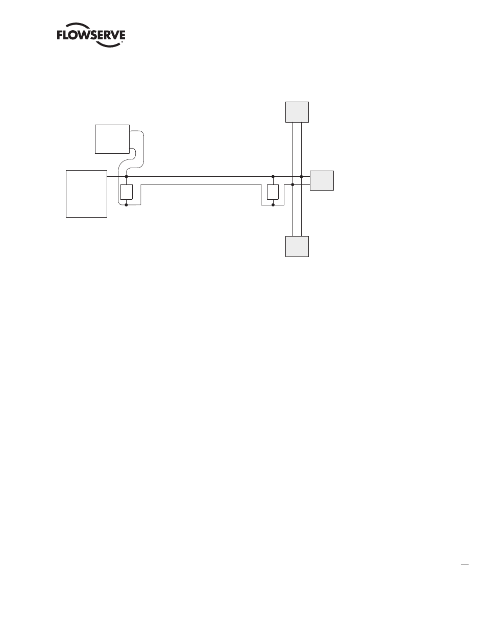
2.2.5.2 PROFIBUS PA Power Supply
The MX/QX PB/PA board requires a nominal 24 VDC (9-32 VDC) on the PA bus to power the MX/QX
PB/PA board and make the actuator visible on the network. The required power supply is typically
connected to a segment coupler to the bus, usually located at the host end of the cable. Validate the
requirements of the segment coupler to determine actual power and voltage.
NOTE: If the actuator does not have three-phase power and the network is active, the MX/QX PB/PA
board will report this condition to the host.
Figure 2.10 shows a typical PROFIBUS PA power supply arrangement.
Figure 2.10 – PROFIBUS PA Power Supply
T
PROFIBUS PA
Interface
+
-
Fieldbus
Power
Supply
Shielded Wire Pair
T
Field
Device
Field
Device
Field
Device
NOTE: Bus power supply may be integrated
with the PROFIBUS PA bus interface.
2.3 Other Network Components
In addition to the network cables, the following components may be used in the PROFIBUS network.
Each network is designed based on its application and therefore may not require all of these
components.
• Bus Terminal Blocks/Junction Box – Provides multiple connections to the bus (network).
• Active Bus Terminal – Provides active termination so that other stations may be powered down for
service without affecting the network.
• Connectors – Enable connections to junction boxes, terminators or other connectors. Useful in
installations where devices will be periodically disconnected or when a device is only going to be
temporarily disconnected. Some PROFIBUS connectors also include termination resistors for line
termination.
• Couplers – Provide one or several connection points to a network segment.
• Repeaters – The PROFIBUS Physical Layer (RS-485) dictates that no more than 32 nodes can exist
in a shielded twisted-pair (copper) segment. A node is defined as any station, active or passive,
that is connected to the network. Media converters (copper to fiber-optic, fiber-optic to copper) and
repeaters do not have PROFIBUS addresses and, therefore, are not included in the 126 possible
addressable nodes.
RS-485 repeaters may be used to extend the recommended distance of a segment and “reform”
the signal to full voltage levels. Repeaters are included in the total number of allowable nodes per
segment; therefore, a segment that begins with a repeater and ends with a repeater may have 30
nodes between them. The maximum number of repeaters allowed in a PROFIBUS network is nine.
(Refer to Figure 2.11.)
• Terminators – Used at each end of a PROFIBUS segment to prevent signal reflections.
• Power Supplies – Different types of power supplies can be used in a PROFIBUS network:
• Non-intrinsically safe power supply.
• Standard linear or switching power supply used with a power conditioner.
• Intrinsically safe power supply (9-32 VDC; nominal 24 VDC for PA).