5 mx/qx pb device setup, Figure 2.21 – profibus dp setup sequence – Flowserve MX/QX Profibus DP/PA Field Unit User Manual
Page 31
31
PB DPV1 / PA Field Unit Installation and Maintenance FCD LMENIM2336-03 – 12/12
flowserve.com
2.5 MX/QX PB Device Setup
The MX/QX PB option enables the actuator to be controlled by a PROFIBUS communications signal.
If the option has been purchased, it is automatically enabled.
NOTE: If the PB option has not been purchased, the screens for changing PB will not be available. To
add the option, please consult Flowserve Limitorque service at (434) 528-4400.
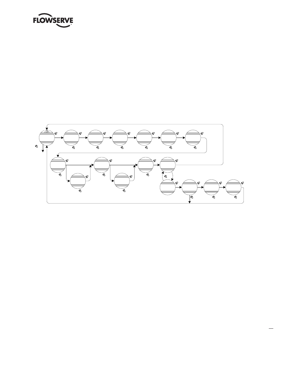
Figure 2.21 – MX/QX PB DP Setup Sequence
CHA NGE
P B/DP ?
P B DP-A S TA TUS
(ON) - OK ?
P B A DDRE S S 1
OK?
A NA LOG S CA LE
0-100-OK?
E S D A CTION
(IGNORE )-OK ?
E S D MOV E TO
(X X X%) - OK ?
COMM LOS S
A CTION
(NONE ) – OK ?
MOV E TO
(X X X%) - OK?
COMM LOS S
DE LA Y
60 S E CS-OK ?
OP E N/CLOS E
MODE - OK ?
P OS ITION
MODE - OK ?
CHA NGE P ROP/
DE A D B A ND?
P ROP B A ND
(15%) - OK ?
P B DP-B S TA TUS
(ON) - OK ?
RE DUNDA NT
MA S TE R
(Y E S) - OK ?
MONITOR
S TA NDB Y P B
(ON) - OK ?
DE A DB A ND
(2%) - OK ?
(0-125)
Unit increments
(0-255)
(0-4095)
(1%-100%)
1% Increments
(1%-50%)
1% Increments
(CLOS E )
(OP E N)
(S TOP )
(P OS ITION )
(0-100%)
(CLOS E)
(OP E N)
(S TOP )
(P OS ITION )
(0-100%)
(0-4095)
*
*
* If P OS ITION is chosen, as action,
this menu will appear.
YES
NO
Figure 2.21 – PROFIBUS DP Setup Sequence
NO
YES
NO
YES
NO
YES
NO
YES
NO
YES
NO
YES
NO
YES
NO
YES
NO
YES
NO
YES
NO
YES
YES
NO
YES
NO
YES
NO
YES
NO
YES
Figure 2.21 illustrates the setup sequence for the MX/QX PB DP field unit. For proper operation, either
Position Mode or Open/Close Mode must be selected.
Follow these steps to enter and configure the setup mode:
1. Proceed through the Setup to the CHANGE PBDP? display.
2. Select YES to proceed to the PBDP-A STATUS (ON)-OK? display. PBDP-A Status enables the
user to change from the default condition to turn on and off the digital control capability of the
actuator.
3. Select YES to proceed to the PBDP-B STATUS (ON)-OK? display. PBDP-B Status enables the user
to change from the default condition to turn on and off the redundant digital control capability of
the actuator, if installed.
4. Select YES to proceed to the REDUNDANT MASTER (YES)-OK? display. Selecting REDUNDANT
MASTER will allow for System Redundancy with two independent connections to Profibus
masters. REDUNDANT MASTER must be set to NO for Flying Redundancy (single Profibus
master connection).
5. If YES is selected, MONITOR STANDBY PB (ON)-OK? is displayed.
6. To allow the standby Profibus master to monitor the health of the actuator’s standby PB DP
board, select YES.