Led indicators, 3 led indicators, 3 led i – Comtech EF Data CRS-400 User Manual
Page 54: Ndicators
CRS-400 1:8 Redundancy Switch
Revision 0
Remote Control
MN/CRS400.IOM
38
3.3 LED I
NDICATORS
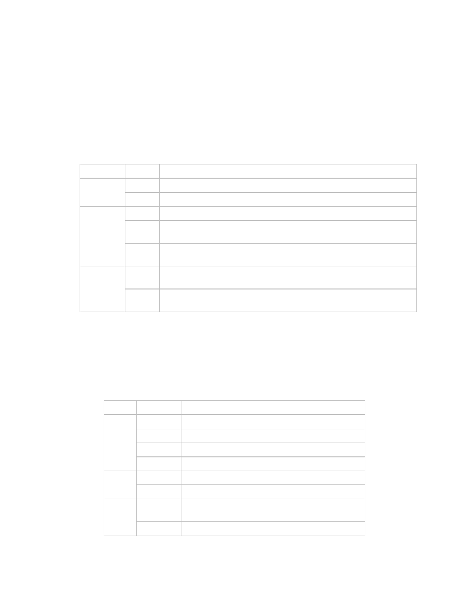
Table 3-1 describes the three LEDs at the top left of the front panel. These LEDs reflect
the condition of the switch itself.
Table 3-1 Switch LED Indicators
LED Color
Condition
Red
A Switch Fault exists
Example: PSU fault or COMMS failure
Unit
Status
Green
No Switch Faults
Off
No Stored Events, Auto Switching On
Orange
Stored Events exist for the switch. Solid Orange or Off indicates switch is
in Auto mode.
Stored
Event
Orange
Flashing
Switch is in Manual mode.
Off
Switch is in Local Mode, remote monitoring is possible, remote
configuration control is not allowed
Remote
Orange
Switch is in Remote Mode, configuration changes are disabled via the
front panel keypad
The front panel contains 3 LEDs (Status, On Line, Bridge) for each traffic modulator and
demodulator connected to the rear of the switch, and 2 LEDs (Fault, On Line) each for
the redundant modulator and demodulator. All of these LEDs are described in Table 3-2.
Table 3-2 Transmit and Receive Traffic Mod/Demod LED Indicators
LED Color
Condition
Red
A Unit Fault exists
Green
No Unit Fault
Orange
TMI is installed but Unit not active
Status
Off
TMI is not installed
Green
The Unit is On Line, and ready to carry traffic
On line
Off
The Unit is Off Line (standby) - forced by the Switch
Orange
(or Yellow)
Unit is currently being Bridged by Redundant Unit
Bridge
Off
Unit is not being Bridged