2 remote (j2) – Comtech EF Data RCS11 User Manual
Page 60
RCS11 1:1 Redundancy Switch
Connector Pinouts
MN-RCS11 – Revision 9
5–2
5.4
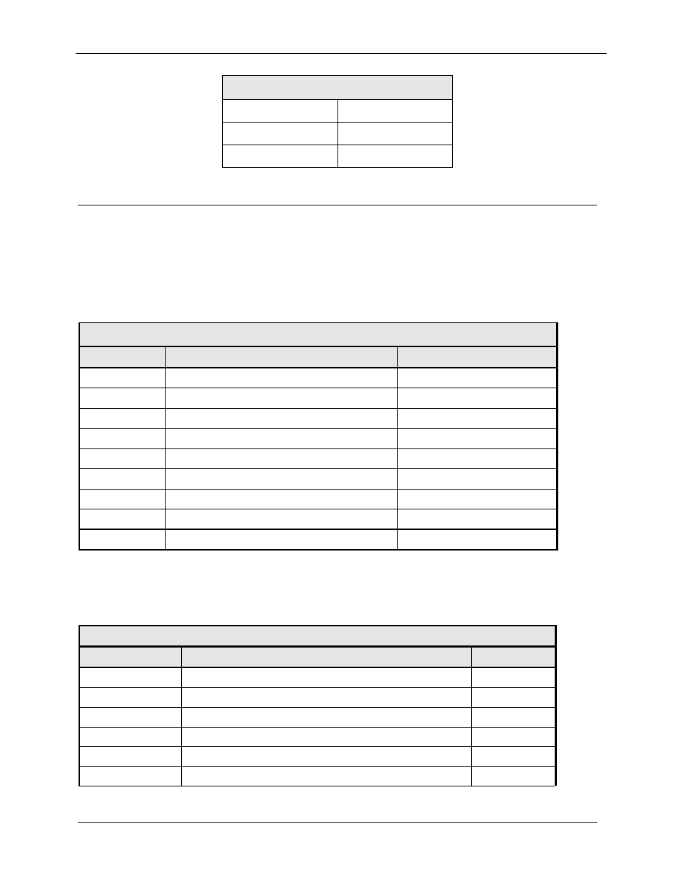
RCS11 COMMON CONNECTIONS
5.4.1 FAULTS (J1)
The Fault Port is a 9-Pin Female ‘D’ Connector. This does not include the HSSI interface. Refer
to Table 5-2 for pinouts.
Table 5-2 Fault Port – 9-Pin Female ‘D’ Connector
Pin No.
Description
Status
1
Switch Fault Relay
Common
2
Switch Fault Relay
Normally Open
3
Mod B Selected Relay
Normally Closed
4
Demod B Selected Relay
Common
5
Demod B Selected Relay
Normally Open
6
Switch Fault Relay
Normally Closed
7
Mod B Selected Relay
Common
8
Mod B Selected Relay
Normally Open
9
Demod B Selected Relay
Normally Closed
5.4.2 REMOTE (J2)
The Remote Control Port is a 9-Pin Female ‘D’ Connector. Refer to Table 5-3 for pinouts.
Table 5-3. Remote Port – 9-Pin Female ‘D’ Connector (J2)
Pin Number
Description
Signal
1
*RS-485 Remote RLLP Select
2 RX
RS232
Input
3 TX
RS232
Output
4 NC
NA
5 Ground
GND
6
RX (A) – RS485
Input
Table 5-1 DC Power
A
-
B Ground
C
+
- CDD-880 (124 pages)
- CDM-800 (130 pages)
- ODMR-840 (184 pages)
- CDM-750 (302 pages)
- CDM-840 (244 pages)
- SLM-5650A (420 pages)
- CTOG-250 (236 pages)
- CDM-700 (256 pages)
- CDM-760 (416 pages)
- CDM-710G (246 pages)
- CDM-600/600L (278 pages)
- CDMR-570L (512 pages)
- CDM-625 (684 pages)
- CDM-625A (756 pages)
- CDD-564A (240 pages)
- CDD-564L (254 pages)
- CLO-10 (134 pages)
- MCED-100 (96 pages)
- CDMR-570AL (618 pages)
- CDM-600 LDPC (2 pages)
- BUC Power Supply Ground Cable (2 pages)
- MPP70 Hardware Kit for CDM-570L (4 pages)
- MPP50 Hardware Kit for CDM-570L (4 pages)
- CDM-625 DC-AC Conversion (4 pages)
- CDM-625 DC-AC Conversion with IP Packet Processor (4 pages)
- DMDVR20 LBST Rev 1.1 (117 pages)
- DMD2050E (212 pages)
- DMD-2050 (342 pages)
- DMD1050 (188 pages)
- OM20 (220 pages)
- QAM256 (87 pages)
- DD240XR Rev Е (121 pages)
- MM200 ASI Field (5 pages)
- DM240-DVB (196 pages)
- MM200 (192 pages)
- CRS-150 (78 pages)
- CRS-280L (64 pages)
- CRS-170A (172 pages)
- CRS-180 (136 pages)
- SMS-301 (124 pages)
- CiM-25/8000 (186 pages)
- CiM-25 (26 pages)
- CRS-500 (218 pages)
- CRS-311 (196 pages)
- CIC-20 LVDS to HSSI (26 pages)