1 digital i/o interface, 1 interface, Digital i/o interface – BECKHOFF EtherCAT IP Core for Altera FPGAs v3.0.10 User Manual
Page 100: Interface, Table 43: ip core digital i/o signals, Table 44: input/output byte reference, Figure 33: ip core digital i/o signals
PDI Description
III-88
Slave Controller
– IP Core for Altera FPGAs
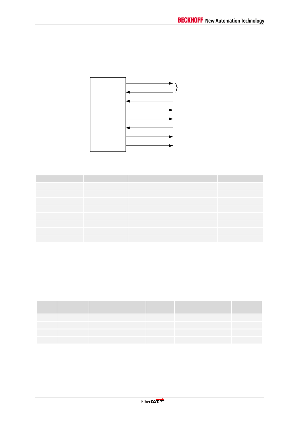
10.1 Digital I/O Interface
10.1.1 Interface
The Digital I/O PDI is selected with PDI type 0x04. The signals of the Digital I/O interface are
2
:
EtherCAT
IP core
DATA_OUT[31:0]
LATCH_IN
OUTVALID
SOF
OE_EXT
WD_TRIG
DATA_IN[31:0]
I/O[31:0]
DATA_ENA
Figure 33: IP core digital I/O signals
Table 43: IP core digital I/O signals
Signal
Direction
Description
Signal polarity
DATA_OUT[31:0]
OUT
Output data
DATA_IN[31:0]
IN
Input data
LATCH_IN
IN
External data latch signal
act. High
OUTVALID
OUT
Output data is valid/Output event
act. High
SOF
OUT
Start of Frame
act. High
OE_EXT
IN
Output Enable
act. High
WD_TRIG
OUT
Watchdog Trigger
act. High
DATA_ENA
OUT
Enable external Output data driver
act. High
NOTE: Unsupported Digital I/O control signal OE_CONF is assumed to be low.
The Digital I/O PDI supports 1-4 byte of digital I/O signals, with each byte individually configurable as
either input or output. At the IP core interface, the I/O signals are separated in input signals
(DATA_IN) and output signals (DATA_OUT). The corresponding I/O bytes and addresses are listed
below.
Table 44: Input/Output byte reference
I/O
Byte
I/O signal
Output signal
Output
address
Input signal
Input
address
0
I/O[7:0]
DATA_OUT[7:0]
0x0F00
DATA_IN[7:0]
0x1000
1
I/O[15:8]
DATA_OUT[15:8]
0x0F01
DATA_IN[15:8]
0x1001
2
I/O[23:16]
DATA_OUT[23:16]
0x0F02
DATA_IN[23:16]
0x1002
3
I/O[31:24]
DATA_OUT[31:24]
0x0F03
DATA_IN[31:24]
0x1003
2
The prefix `PDI_DIGI_` is added to the Digital I/O interface signals if the EtherCAT IP Core is used.