Commlink iv dip switch setting, Figure 2-34: commlink iv dip switch setting, Figure 2-35: commlink iv to zone manager wiring – Auto-Zone Control Systems Auto-Zone Plus Systems Installation & Operation (Version 03A) User Manual
Page 79
Auto-Zone Plus
Section
2
Design Guide
2-47
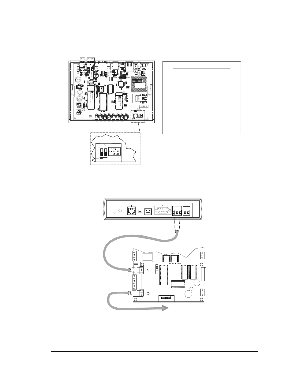
CommLink IV DIP Switch Setting
DIP Switch 1 & 2 Off =
Multiple Loop Communications
Required Setting For Auto-Zone Plus System
CommLink IV Communication Settings
The SW1 DIP Switch Located On The Circuit Board Inside
The CommLink IV Housing Must Be Set Correctly For
Your Specific Application In Order To Function Properly.
To Check And/Or Set The SW1 Dip Switch, First Remove
The (2) Enclosure Screws That Hold The Top And Bottom
Of The CommLink IV Enclosure Together. Remove The
Top Half Of The Enclosure To Access The Circuit Board
And Dip Switches.
The
DIP Switch Setting Should Be Set To “Multiple”
For The Auto-Zone Plus System
The CommLink IV Is Factory Set For Multiple Loop
Applications.
SW1
Replace The CommLink IV Cover And Secure The
Enclosure Halves Back Together With The (2) Enclosure
Screws That Were Previously Removed.
ALTERA
EPM3032
WattMaster Controls Inc.
COMMLINK IV
YS102074
REV6
MADE IN USA
Figure 2-34:
CommLink IV DIP Switch Setting
MODEM
RS-232
Serial #
COMPUTER
USB
10/100
ETHERNET
DIAG
24V
T G R
GN
D
485 LOOP POWER
ACT
LNK
USB
Co
nf
ig
No
rm
al
Local Communications Loop
To Zone Controllers
And System Manager
HEAT2
HEAT1
COOL2
COOL1
FAN
R
8
C
S
W
1
16
A
B
2
4
A
D
D
LOCAL
LOOP
T
SH
R
TB3
COMM
T
SH
R
32
16
8
4
1
2
V4
V3
CLOSE
OPEN
FDBK
GND
NETWORK
LOOP
Network
Comm Loop
Local
Comm Loop
SH
R
T
CLOSE
K
2
ANALOG
OUTPUTS
A2
G
TB2
A1
T
R
SHIELD
T
R
SHIELD
T
R
SH
IE
LD
Figure 2-35:
CommLink IV to Zone Manager Wiring