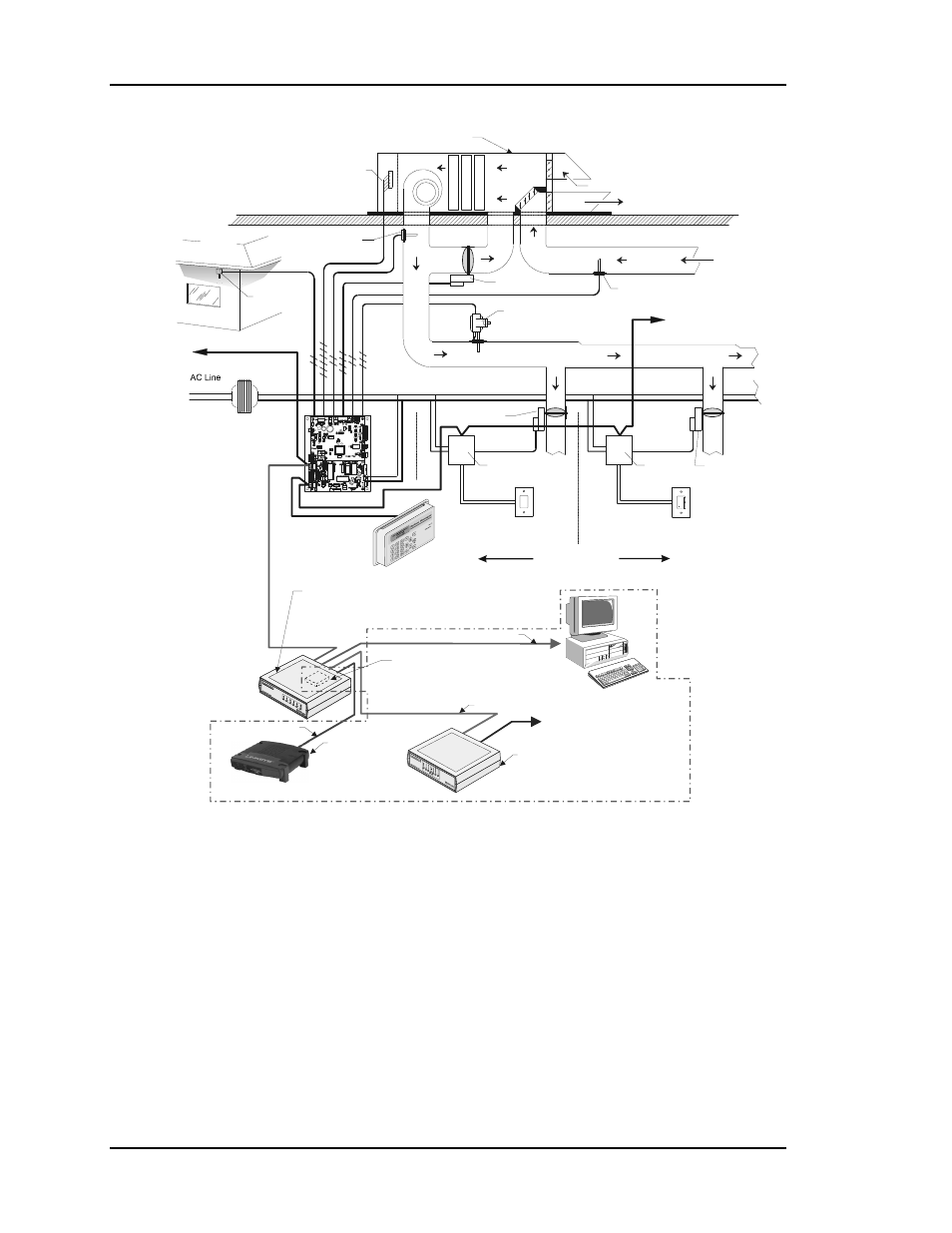
Plus 2-6 design guide, Figure 2-1: plus system overview, Norma l warmer co ol er ovr – Auto-Zone Control Systems Auto-Zone Plus Systems Installation & Operation (Version 03A) User Manual
Page 38
Section 2
Auto-Zone
Plus
2-6
Design
Guide
NORMA L
WARMER
CO OL ER
OVR
Connect To Other
Zone Managers
Connect To Other
Zone Controllers Or
CV Units
Voltage
Supply Air
Temperature Sensor
Modulating Bypass
Damper
Zone
Controller
Zone
Controller
Zone Manager
Modulating Zone
Damper
Modulating Zone
Damper
Control Cable
Typical Rooftop HVAC Unit
Outdoor Air
Mixed Air
Return Air
Exhaust Air
Static Pressure Sensor
& Pickup Tube
24 VAC
Local Comm Loop
System Manager
Network Comm Loop
Ground
Supply Fan
Supply Air Duct
HI
LO
Return Air
Temperature Sensor
Zone 2
Space Temperature Sensor
W/ Override & Setpoint Adjustment
Zone 1
Space Temperature Sensor
Plain
UP TO 16 ZONES
Outdoor Air
Temp. Sensor
Avoid Direct
Sunlight
2 Conductor
24 GA.
2 Conductor
24 GA.
2 Conductor
24 GA.
3 Conductor
24 GA.
120/24 VAC
Transfomer
Optional IP Module
Installs Into CommLink IV
And Provides
LAN And Internet Communications
With The Control System
Optional Personal Computer
Ethernet Router
(By Others)
When IP Module
Option Is Used
All Components Shown Inside This Box Are Optional
Optional Remote Link II
Connects to CommLink IV
And Provides Dial-up Modem
Communications
With The Control System
Phone Cable To Telephone
Wall Outlet Jack
Serial Cable To Remote Link
Ethernet Cable To Router
CommLink IV
Use Of The CommLink IV Is Required For All Multiple Loop
Networked Systems. The IP Module, Remote Link II And
Computer Are Optional. All Computers Used Require The
Be Installed.
Prism
Graphical User Interface Software
USB Cable To Computer
H
ea
tin
g C
oil
Co
ol
in
g C
oi
l
F
ilt
er
Ba
nk
Figure 2-1:
Plus System Overview