Cv controller components, Figure 2-19: cv controller - components – Auto-Zone Control Systems Auto-Zone Plus Systems Installation & Operation (Version 03A) User Manual
Page 61
Auto-Zone Plus
Section
2
Design Guide
2-29
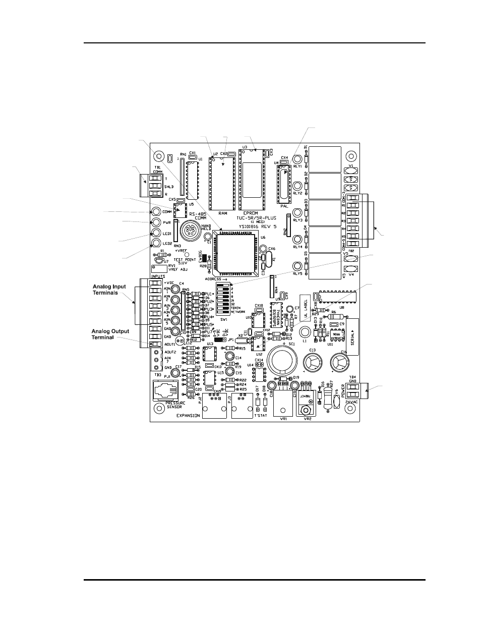
CV Controller Components
Relay Outputs
Terminals
Diagnostic Blink
Code LED 1
Diagnostic Blink
Code LED 2
RS-485
Communications
Terminal Block
CPU
Chip
Typical
Pin 1
Indicator
RAM
Chip
EPROM
Chip
PAL
Chip
RS-485
Communications
Driver Chip
Real Time
Clock Chip
Communications
LED
Address Switch
Power LED
24 VAC
Power Input
Terminal
Figure 2-19:
CV Controller - Components