11 comm driver chip replacement, Figure 4-6: communication driver chip locations – Auto-Zone Control Systems Auto-Zone Plus Systems Installation & Operation (Version 03A) User Manual
Page 170
Section 4
Auto-Zone Plus
4-20
Start-Up and Troubleshooting
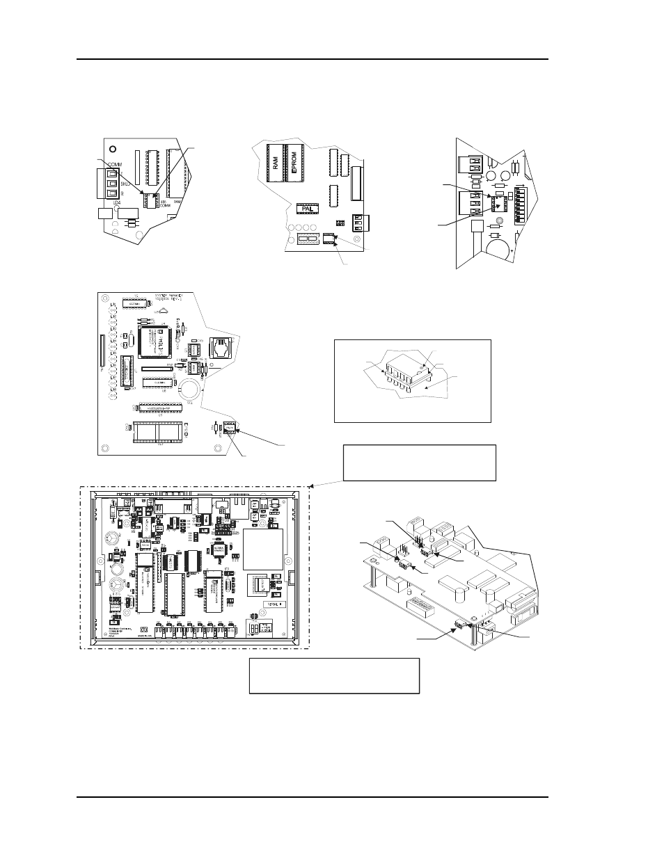
1.3.11
Comm Driver Chip Replacement
Pin 1
Dot
Socket
Printed
Circuit
Board
Typical RS-485 Communications
Driver Chip Detail
Comm Driver Chip
( U10 )
Pin 1
1
2
4
8
16
ADDRESS
T'STAT
CO
M
M
PO
W
E
R
Zone Controller
Lighting Panel Controller
System Manager
Pin 1
Commlink IV
Comm Driver Chip
(U12)
Caution: Comm Driver Chip Is Not Field Replaceable
On The CommLink IV! If You Suspect The Driver Is
Damaged It Must Be Returned To The Factory For
Repair Or Replacement. Do Not Try To Remove The
Chip Yourself Or You Will Damage The CommLink.
CV Controller,CV-C Controller
GPC Plus Contoller, Wetbulb Module
Pin 1
Pin 1
Comm Driver Chip
( U5 )
Comm Driver Chip
( U3 )
Warning!
Use Extreme Caution When Removing Any Chips
To Avoid Damaging Any Circuit Board Traces Which
Are Under The Chip.
A Small Screwdriver May Be Inserted Between The
Chip And The Socket To Aid In Removal Of The Chip.
Be Very Careful Not To Insert The Screwdriver Under
The Socket!! Damage To The Board Is Not Covered
By Warranty.
Zone Manager
Network Loop
Comm Driver Chip
( U5 )
Local Loop
Comm Driver Chip
( U8 )
Zone Manager
Comm Driver Chip
( U15 )
Pin 1
Pin 1
Pin 1
T
SH
R
Figure 4-6: Communication Driver Chip Locations