3 troubleshooting – Auto-Zone Control Systems Auto-Zone Plus Systems Installation & Operation (Version 03A) User Manual
Page 182
Section 4
Auto-Zone Plus
4-32
Start-Up and Troubleshooting
2.3 Troubleshooting
2.3.1
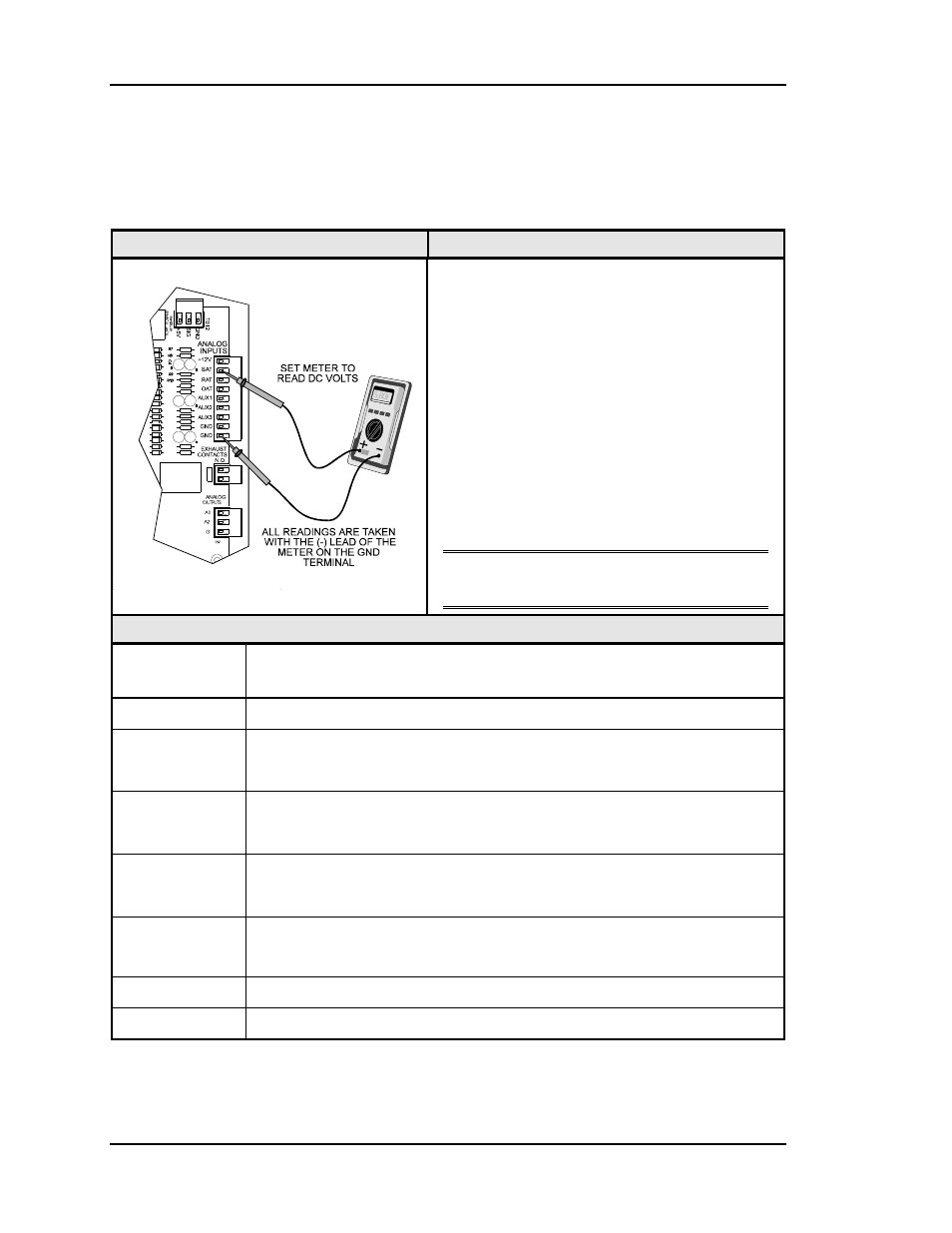
Checking the Zone Manager Analog Inputs
Diagram
Overview
The analog input wiring can be checked at the
Zone Manager by checking voltages on the
Analog Input Connector.
If any of the RAT, SAT, OAT inputs read
greater than 5.0 volts then it is OPEN (no
sensor is connected), an input that reads less
than 0.1 volts is SHORTED. Check for wiring
problems before proceeding.
The AUX1-3 inputs should read greater than
5.0 volts if the attached contact is OPEN and
less than 0.5 volts if the contact is CLOSED
(contacts CLOSE between the input and
GND).
Note: The Zone Manager must be powered
for these tests.
Measurements
Meter Acceptable
Range
Ignore readings for any connections which are not used in the equipment
+12
23.4 – 25.2 volts
SAT
1.1 volts (140
°F) - 3.6 volts (40°F)
Typical is 2.5 volts @ 77
°F
RAT
1.9 volts (100
°F) - 3.6 volts (40°F)
Typical is 2.5 volts @ 77
°F
OAT
1.9 volts (100
°F) - 4.6 volts (-10°F)
Typical is 2.5 volts @ 77
°F
AUX1
If the input is OPEN, the voltage will be greater than 5.0 volts
If the input is CLOSED, the voltage will be less than 0.5 volts
AUX2
see AUX1 above
AUX3
see AUX1 above