Minimum, Default, Maximum – Auto-Zone Control Systems Auto-Zone Plus Systems Installation & Operation (Version 03A) User Manual
Page 121: Setpoint screen #5, Setpoint screen #6, Setpoint screen #7
Auto-Zone Plus
Section 3
Programming
3-35
Setpoint Screen #5
Setpoint Screen #6
Note: If the direction is changed, you will need to cycle power to the Zone
Controller so it can re-calibrate the damper feedback limits.
Setpoint Screen #7
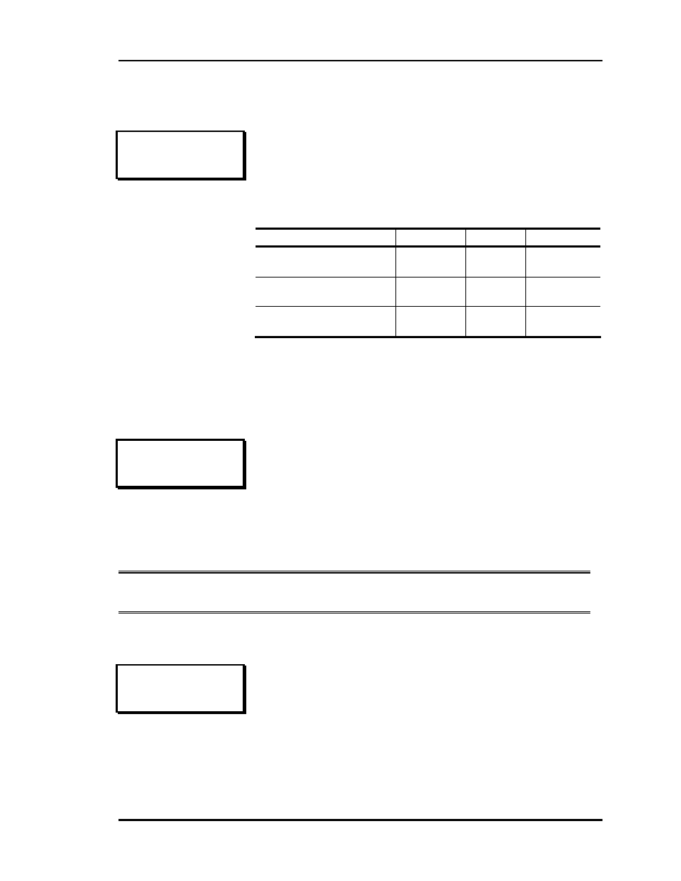
PD ZONE ADDRESS 1
Vent Mode Min.: 50%
Nite Mode Min.: 100%
CFM @ 1"WG: 2100 cfm
On Pressure Dependent Zones, these setpoints are for damper
position, on Pressure Independent Zones they are for Airflow
(CFM) values, and the text will change to reflect that. The last
line is not shown on Pressure Dependent Zones. On the line
that reads CFM @ 1” WG enter the appropriate “K” Flow
Factor from Table 1-3 of this manual
Minimum
Default
Maximum
PD Zone Vent Mode Min
PI Zone Vent Mode
0 %
0 CFM
50 %
500 CFM
100 %
30000 CFM
PD Zone Nite Mode Min
PI Zone Nite Mode
0 %
0 CFM
100 %
0 CFM
100 %
30000 CFM
CFM @ 1" WG
0 CFM
2100
CFM
30000 CFM
PD ZONE ADDRESS 1
Overrides..: Global
Damper Mode: Direct
Use Left/Right Arrow
The Zone Controller will respond to another zone’s pushbutton
override if it is configured for global overrides. If single
overrides are selected, the zone will only enter override if its
own pushbutton is pressed.
The normal damper operation is direct acting, which means it
opens in a clockwise direction. If your Damper opens in a
counter-clockwise direction, select reverse acting mode.
PD ZONE ADDRESS 1
Voting Mode: Voting
Use Left/Right Arrow
Normally, you want a zone to be included in the polling by the
Zone Manager. This allows the demand in that zone to have a
vote in determining the HVAC mode of operation. If you have
a problem zone or an area that you don't want to include in the
voting, select the NonVote mode of operation.