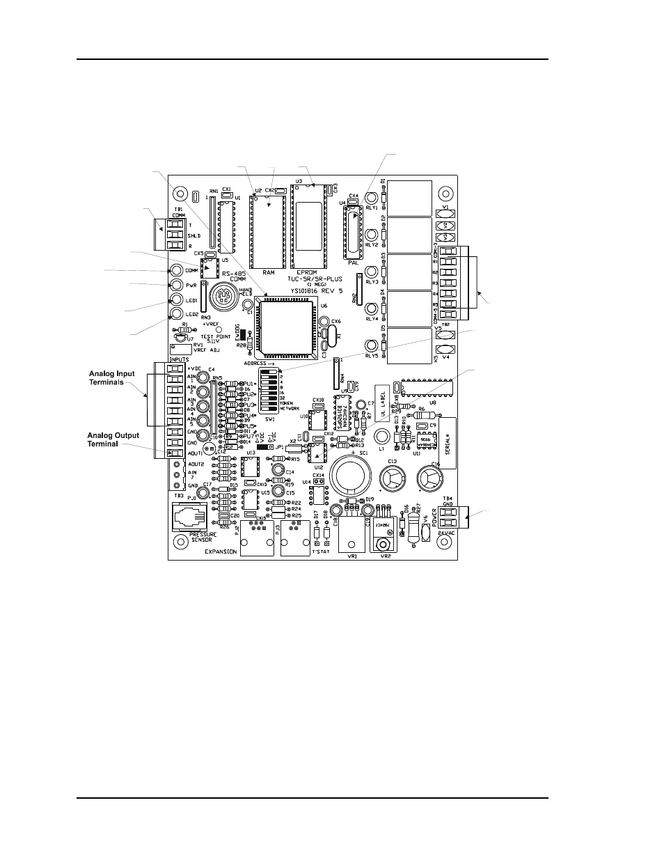
2 becoming familiar with the cv controller, 1 24 vac power connector, Figure 4-14: cv controller component layout – Auto-Zone Control Systems Auto-Zone Plus Systems Installation & Operation (Version 03A) User Manual
Page 196
Section 4
Auto-Zone Plus
4-46
Start-Up and Troubleshooting
4.2 Becoming Familiar with the CV
Controller
Relay Outputs
Terminals
Diagnostic Blink
Code LED 1
Diagnostic Blink
Code LED 2
RS-485
Communications
Terminal Block
CPU
Chip
Typical
Pin 1
Indicator
RAM
Chip
EPROM
Chip
PAL
Chip
RS-485
Communications
Driver Chip
Real Time
Clock Chip
Communications
LED
Address Switch
Power LED
24 VAC
Power Input
Terminal
Figure 4-14:
CV Controller Component Layout
4.2.1
24 VAC Power Connector
This connector provides power to the CV Controller.
24VAC - The “hot” side of the control transformer.
GND - The grounded side of the control transformer. If the secondary of the
control transformer is not grounded, you must still observe polarity if the
transformer powers any other device!