Zone controller wiring & addressing – Auto-Zone Control Systems Auto-Zone Plus Systems Installation & Operation (Version 03A) User Manual
Page 55
Auto-Zone Plus
Section
2
Design Guide
2-23
Zone Controller Wiring & Addressing
Notes:
R
SH
T
R
SH
T
R
SH
T
R
SH
T
All Comm Loop Wiring Is
Straight Thru
Required VA For Transformer
Each Zone Controller = 10 VA Max.
(Includes Actuator)
24VAC
GND
GND
AUX
TMP
NORMAL
OVR
R
E
L
O
C
R
E
M
R
O
A
W
16
32
TOKEN
NET
8
4
2
1
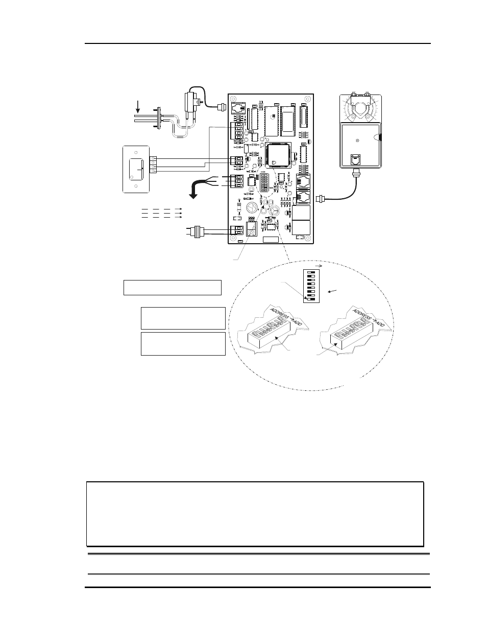
Caution!
Zone Controllers Must Have Address Switches Set Between
1 And 16 ( Up To 16 Zone Controllers Per Local Loop ).
Room Sensor
Diagnostic Blink Code LED
Zone Actuator
Zone Controller
Local Loop
RS-485
9600 Baud
Airflow Sensor (Optional)
Only Used For Pressure
Independent Applications
Connect To
Next Controller
And/Or Zone
Manager On
Local Loop
Address Switch Shown Is
Set For Address 9
Address Switch Shown Is
Set For Address 13
Controller
Address Switch
This Switch Must Be
In The ON Position
As Shown
Switches Labeled 32 And
Token Should Be In The
OFF Position As Shown
Note:
The Power To The Zone Controller Must Be
Removed And Reconnected After Changing The
Address Switch Settings In Order For Any Changes
To Take Effect.
Caution:
Disconnect All Communication Loop Wiring
From The Zone Controller Before Removing Power
From The Zone Controller. Reconnect Power And
Then Reconnect Communication Loop Wiring.
ADDRESS ADD
The Address For Each Controller
Must Be Between 1 And 16 And Be
Unique To The Other Controllers
On The Local Loop
Connection To AUX
Terminal Required Only
When Sensor Is Specified
With Slide Adjust Option
1.)24 VAC Must Be Connected So
That All Ground Wires Remain
Common.
2.)All Wiring To Be In Accordance
With Local And National Electrical
Codes And Specifications.
3.)AllCommunication Wiring To Be
2 Conductor Twisted Pair With
Shield. Use Belden #82760 Or
Equivalent.
1
0
SHIELD
R
T
Hi
Lo
Ai
rf
lo
w
CX4
R2
8
R24
7
824
GND
R17
R16
U7
PO
W
E
R
R26
YS
101
562
RE
V
. 3
24VAC
D4
VR
1
L1
C7
D3
SCA
N
R2
1
RE
C
C6
R1
4
CX10
U1
1
COMM
C1
5
R25
SW
1
U1
0
16
32
NET
4
8
2
1
U6
ADDRESS
EW
DO
G
C1
1
R2
0
R1
9
ADD
VR
EF
ADJ
T'STAT
R32
D6
C1
4
C1
3
R27
C8
R23
C1
0
P.U.
R22
CX9
C9
U9
U8
D5
RN
1
AIRFLOW
R3
4
R1
8
CX8
U4
R1
5
Q3
D2
K2
V2
PJ2
R1
00
R1
2
R1
1
Q2
D1
K1
R9
R13
V1
AC
TU
A
T
OR
C4
R8
CX6
C5
C3
PJ1
CX
5
R6
R7
R5
R4
C2
EX
P
A
N
S
IO
N
CX2
PA
L
X1
C1
EPROM
R1
R2
R3
U2
Q1
CX1
U3
CX3
U1
P.U.
O
I
D7
R33
U5
P.U.
48
5
DR
V
C16
V3
R3
5
PJ3
OF
F
Figure 2-14:
Zone Controller Wiring & Addressing
Set the Zone Controller Address Switch following the following addressing
instructions.
Caution:
Incorrect addressing is the number one cause of communication
problems. Check the addressing carefully. Remember, the Zone
Controller only reads the switch during a power-up. If the address
switch is changed, the unit must be turned OFF then ON before the
new setting will be recognized.
Note:
Ignore any markings or numbers on the switch. Use this chart!