Figure 4-3: network loop wiring – Auto-Zone Control Systems Auto-Zone Plus Systems Installation & Operation (Version 03A) User Manual
Page 157
Auto-Zone Plus
Section 4
Start-Up and Troubleshooting
4-7
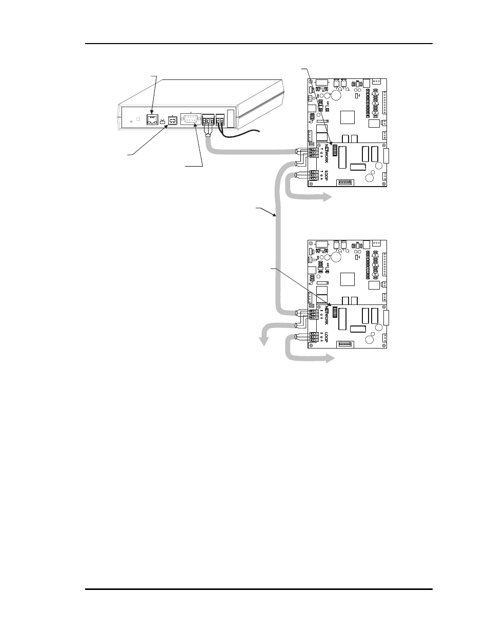
To Other
Auto-Zone Plus
Zone Managers
Caution!
Assure That The Network Loop Only
Connects To Zone Manager Network Terminals.
Do Not Connect Anything Other Than Zone Managers
And The Com Link IV To The Network Terminals.
m
HVAC Unit #1
Zone Manager
HVAC Unit #2
Zone Manager
Address
Switch Set To 1
Address
Switch Set To 1
Local Loop #1
Local Loop #2
To HVAC Unit #1
Zone Controllers
And Constant Volume
Units If Used
To HVAC Unit #2
Zone Controllers
And Constant Volume
Units If Used
T
R
SHLD
T
R
SHLD
To Remote Link II
Modem Using Supplied
Serial Cable
(Optional )
Connect To Router (By Others) With
Supplied CAT5 Cable When
Using IP Module Kit
(Optional )
To Computer
(Optional By Others)
Using Supplied
USB Cable
(Optional )
Network Loop
To
24 VAC
Power
Supply
CommLink IV
MODEM
RS-232
Serial #
COMPUTER
USB
10/100
ETHERNET
DIAG
24V
T G R
GN
D
485 LOOP POWER
ACT
LNK
USB
C
onf
ig
No
rm
a
l
Figure 4-3:
Network Loop Wiring