Cv-c controller, General, Figure 2-22: cv-c controller dimensions – Auto-Zone Control Systems Auto-Zone Plus Systems Installation & Operation (Version 03A) User Manual
Page 65
Auto-Zone Plus
Section
2
Design Guide
2-33
CV-C Controller
General
The CV-C Controller is very similar to the CV controller except the OE331 CV-C
Controller is a configurable controller that allows for user configurable inputs and
outputs. CV-C Controllers also have provisions for mounting a Relay Expansion Board to
provide additional heating or cooling staging capability. It cannot be programmed
Caution
: The CV-C controller requires the use of a personal computer with Prism
software installed for programming and monitoring of the controller.
Unlike the CV controller the System Manager cannot communicate with
the CV-C Controller.
The CV-C Controller may be installed in any convenient protected location. Observe the
recommended environmental limitations for the CV-C Controller. It should not be
mounted in locations subject to extreme low or high temperatures (below 20° F or above
140° F) or in damp or wet environments (maximum of 90% RH). If it is to be mounted
outdoors it must be enclosed in weathertight enclosure.
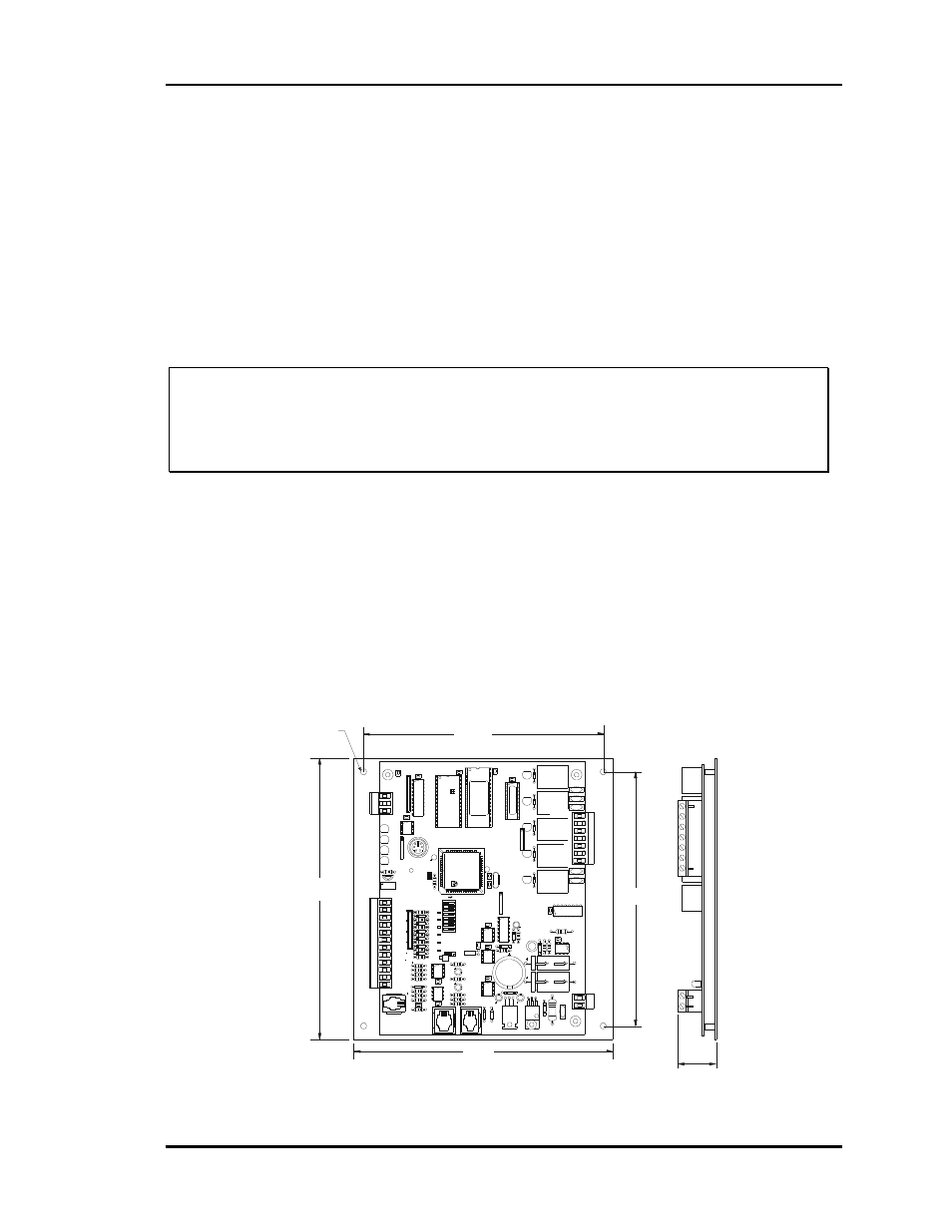
The CV-C Controller may be mounted without removing the controller from the
mounting plate. The unit is mounted by securing with four (4) screws through the
mounting holes in the mounting backplate. Select the correct screws or other fasteners for
the type of mounting material being utilized.
RL
Y
1
D1
D2
D3
D4
D5
CX
3
RAM
EPROM
C3
C2
U6
P
H
IL
IP
S
CX6
C1
CX2
U2
U3
PAL
CX4
U4
TUC-5R PLUS
YS101816 REV. 2
V1
V2
V3
V5
V4
TB2
4
NETWORK
TOKEN
16
32
8
SW1
ADD
2
1
ADDRESS
V6
PO
W
E
R
GND
24VAC
L1
D1
6
R6
C9
SC1
R1
1
U1
1
MC
34064
A
D1
3
C16
9936
VR2
7824C
T
M
TB4
R2
7
C13
R1
0
VR1
C1
9
C1
8
NE5090NPB3192
0PS
U8
CX
8
U9
X1
R7
D1
0
R13
D12
C7
CX10
U10
CX12
U12
U14
CX14
PJ
3
PJ
2
PJ1
EXPANSION
PRESSURE
SENSOR
T'STAT
C17
D15
R26
C20
R25
R24
R22
U15
CX13
U13
C15
R19
R15
C14
D1
8
D1
7
PU1
PU2
PU3
PU4
PU5
PU7
D6
D7
D8
D9
D11
D14
C12
C10
0-
5
VD
C
0-
1
VD
C
JP1
C1
1
X2
GND
TB3
INPUTS
GND
GND
+VDC
AIN1
AIN2
AIN3
AIN4
AIN5
AOUT1
AOUT2
AIN7
RN4
1
RN5
RS-485
CX5
U5
R
TB1
SHLD
T
COMM
COMM
RN3
1
RN1
U1
CX1
1
LD6
COMM
PWR
LD7
LED1
LED2
LD9
LD8
R1
U7
RV1
VREF ADJ
R28
+VREF
5.11V
TEST POINT
EWDOG
D19
RN2
1
COM1-3
COM4-5
R5
R4
R3
R2
R1
RL
Y
2
RL
Y
3
RL
Y
4
RL
Y
5
CX15
(1 MEG)
HH
P1
C2
1
6.2“
6.6”
7.3”
6.7”
1.1”
.20 Dia.
Typ. of 4
Figure 2-22:
CV-C Controller Dimensions