Step #7 - sizing zone dampers, Round air damper selection, Round zone damper selection – Auto-Zone Control Systems Auto-Zone Plus Systems Installation & Operation (Version 03A) User Manual
Page 26
Section 1
Auto-Zone Plus
1-22
Design Guide
Step #7 - Sizing Zone Dampers
Use a load program to determine the peak load for each zone. These calculations will be
used in selecting the appropriate zone damper sizes. WattMaster can provide either round
zone dampers or rectangular zone dampers for your zones
Using the maximum acceptable velocity for a branch duct (typically 1000-1500 FPM for
minimal noise), find the smallest damper that will deliver the required CFM as
determined by the load program.
Round Zone Damper Selection
Locate the branch velocity used in the duct design program on the left hand column of the
damper sizing chart (Table 1-1). Move across the chart and find the damper which will
provide the acceptable CFM to meet zone requirements.
Note:
Compare the damper size selected against the duct size to determine if the
next size up or down will provide acceptable performance without requiring a
transition fitting.
One additional damper may be slaved together for large zones. See zone wiring diagram
for details. This should be reserved for situations when it is not practical to use a single
large damper.
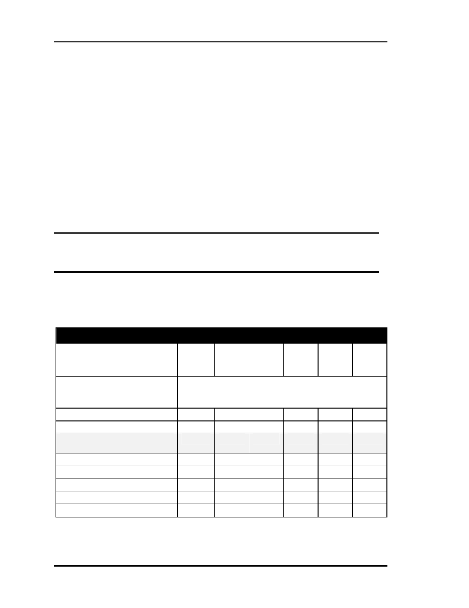
Table 1-1:
Round Damper Sizing Chart
Round Air Damper Selection
Air Damper Round Duct Size
( Area Ft
2
)
6
″
(0.188)
8
″
(0.338)
10
″
(0.532)
12
″
(0.769)
14
″
(1.050)
16
″
(1.375)
Velocity through Round Air
Damper
(FPM)
Volume through Round Air Damper
(CFM)
750 - P.I. or P.D. Zone
141 254 399 577 788 1031
1000 - P.I. or P.D. Zone
188 338 532 769 1050 1375
Maximum CFM For P.I. Zone
Damper
206
413
634
921
1264
1608
1250 – P.D. Zone Only
235 423 665 961 1313 1718
1500 – P.D. Zone Only
282 507 798 1154 1575 2062
1750 - Bypass Only
329 592 931 1346 1838 2405
2000 - Bypass Only
376 676 1064 1538 2100 2749
2250 - Bypass Only
423 761 1197 1730 2363 3094